This tab is in the Slab and Shell Reinforcement dialog and defines reinforcement zones and reinforcement presentation and modification.
The dialog consists of the following.
- Reinforcement zone definition: automatic / manual (working mode definition).
- Selection of lists of solutions.
- Presentation fields of real (provided) reinforcement for a selected solution.
Definition of Reinforcement Zones
this determines real (provided) reinforcement zones in either automatic or manual modes.
The automatic mode generates reinforcement zones and calculates a real (provided) reinforcement area on the accepted reinforcement parameters base, calculation options, and on the bases of calculated earlier theoretical (required) reinforcement areas.
Reinforcement zones are determined by optimizing algorithms. When calculations are completed, you can select from a list of the available solutions.
To optimize reinforcement zones, several factors should be taken into consideration. Optimization of wire fabric reinforcement aims at the following.
- Cut number to achieve the appropriate cuts.
- Mass of reinforcing wire fabrics.
- Usage ratio for wire fabrics.
For bar reinforcement in a spacing modularity, an decrease of the used bars or a used steel mass is preferred.
Manual mode allows defines real (provided) reinforcement zones. In this case you can select the appropriate reinforcing bars and wire fabrics (on a base of the calculated theoretical (required) areas, reinforcement parameters and calculation options).
After selecting the Manual option of a zone definition, the cursor changes to a crosshair, to insert the zones in the graphic viewer.
A definition method of reinforcement zones is similar to that of rectangular contours. It depends on a determination of two points. The first click results in the first corner definition. The second results in a opposite corner definition.
Solution List
Select one of several possible solutions sorted according to an optimization coefficient. This coefficient is the weighted average of the parameters for optimization. Solutions facilitating reinforcment are preferred to those requiring less steel.
When selected, the solution list includes a number and type of used wire fabrics, the percent of wire fabric consumption, and a total mass of wire fabrics with wastes.
For bar reinforcement, estimate quantity survey for bar types is given on the solution list and the quantity survey for total steel weight is not given. In these results the mass is a result of the demanded bar laps and structural reinforcement.
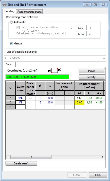
Manual Definition of Reinforcement Zones
To add a reinforcement zone manually select a table row marked with an asterisk. Click on the Coordinates field. Coordinates can be defined manually or by indicating a zone graphically on the screen. Coordinates of the bottom left and top right zone corner are determined for a selected zone.
The selected zone is highlighted in the table presenting the reinforcement values and in the viewers presenting the top and bottom reinforcement zones. The active zone can be modified and it is possible to define a successive zone by pressing the Add button. You can select a row marked with an asterisk and define a zone graphically. In the lower part of the dialog is the Delete reinforcement button that deletes reinforcement in all zones. The table for manual modification of member reinforcement zones differs from that for automatic modification.
Zone. A generated zone may be assigned a user defined name.
Basic panel parameters. Determines if a selected zone is a base or dependent. Choose only those zones that are not dependent. Bars of a dependent zone are distributed symmetrically between bars of the base zone.
ϕ. Diameter of bars.
S. Bar spacing.
Increase of zone reinforcement. Active only for dependent zones. The n+ field determines how many bars of a dependent zone will be placed between bars of the base zone. One base zone may have several dependent zones. Reinforcement of the base zone is increased symmetrically and after selecting a number of bars for the first dependent zone, remaining zones will have limited reinforcement in the list. Diameters of reinforcing bars may be increased, but only when the number of bars n+ differs from zero.
At. Required area (if the zone is not needed since another zone covers entirely the same area and ensures the required reinforcement area, this is highlighted in yellow).
As. Difference between the required and the provided areas.
Ar. Provided area.
Zone displayed. The zone displays when selected.
Fitted zone. Used if a zone is positioned on more than one panel or a panel of untypical shape such as semicircular. Activating this option results in fitting bars in the zone to the panel (bars will not extend outside the panel edge).
Base panel. If a zone covers more than one panel, it is necessary to select a panel to which the zone should be ascribed (to determine the reinforcement direction or to fit the zone, for example.)