Open the GAMMA Angle dialog, which is used to change the position of a member section's local axes, using either method:
- Click Geometry menu > Properties > Gamma Angle.
- Click
 .
.
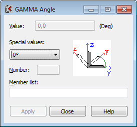
To define a GAMMA angle:
- Select the members for which you want to change the position of the local coordinate system. Enter the member numbers in the Member List field or perform a graphic selection.
- Enter the Gamma angle value.
- Click Apply.
You can enter a value of the Gamma angle using one of the following methods:
- Enter or select the numerical value for the selected member angle (fields: Value or Special values).
- Select the node (the Node option in the Special values field) together with the member nodes, defines the main bending plane of the member section.
- Select the member (the Position option in the Special values field and the Number option). The selected members are turned in such a manner that one of the cross-section principal axes is perpendicular to the longitudinal axis of the highlighted member. This option is useful when setting roof purlin members. The consecutive stages for determining a Gamma angle for structure roof members are shown in the following images.
|
Initial position of members |

|
After defining a Gamma angle, the following members are selected:
|

|
Position of the members after defining a Gamma angle. |
It is assumed that the positive angle is defined according to the right-twist rule.
Note: For 3D frames, the GAMMA angle can be any values in the range between (-360°, 360°).For 2D structures, the GAMMA angle must be a multiple of a 90° angle. Members in 2D structures can be rotated only by the angles: ±90°, ±180°, or ±270°. For a 2D structure, if a different value is defined for a GAMMA angle,
Robot automatically performs an additional rotation, so the GAMMA angle is a multiple of a 90° angle.
The following image of a member structure shows different methods for defining Gamma angle values.
Note: The rotation of a local system (for all structure types,except for 3D frames, shells, andvolumetric structures) affects only the position of a section and not the loads in a local system. Loads in a local system always correspond to the initial system settings. For 3D frames, shells, and volumetric structures, the rotation of a local coordinate system results in rotating the load as well, if it was defined in the local system.
See also: