Click ![]() or select Results > Maps (panels) to present maps or isolines of displacements, moments, and stresses obtained during structure analysis.
or select Results > Maps (panels) to present maps or isolines of displacements, moments, and stresses obtained during structure analysis.

The dialog contains the following tabs
Results obtained for planar finite elements are presented in local coordinate systems which is user defined and modified at any moment of result presentation. Results obtained for structures which contain planar FE may be presented in the form of isolines or color maps on selected elements. The Values option is also available which selects With description by default. Plate or shell structure value descriptions in element centers will then present without drawing maps or isolines.
Only one value may be presented in a dialog. To display other value maps, do one of the following.
- Select the value and click OK. The map of the selected value will replace the current map.
- Select this value and select Open a New Window. The map of the selected value will be presented in a new window and the map of the previous value remain.
Presented maps/isolines may be displayed in three ways.
- With description. If selected, maps are presented with a description of the values of individual isolines.
- With normalization. If deselected, maps of a chosen quantity are presented in such a way that the scale is adjusted to the maximum and the minimum value of the selected quantity.
- With FE mesh. If FE mesh is selected, a map of a chosen quantity and a generated finite element mesh are presented.
Smoothing (averaging of values).
Results for planar FEs are determined at Gauss's points located inside each element. Results estimated at the common node of adjoining elements may differ slightly in each element, and isolines may not be continuous. To obtain a smooth map of a selected quantity, select the with smoothing option. This results in averaging of the values at a node based on all the values obtained in the elements adjoining the node.
Smoothing can be performed in the following ways.
- No smoothing.
- Global smoothing, smoothing according to selection. Smoothing takes no account of the panels to which the elements belong. The selection of the finite elements are recognized.
- Smoothing within a panel. Smoothing takes account of the panels to which the elements belong. Values on the border of 2 elements are smoothed only when they belong to one panel.
The X and Y axes are local and defined using the Direction option on the Detailed tab. This defines the direction of the main local coordinate system which will be used (x axis). The results values for all elements are calculated to this rotated coordinate system. When selecting the results for planar FE, the direction may be defined by entering any vector defining the main direction. The selected vector is then projected onto an element which in the end defines the positioning of the local x-axis. The main vector can not be perpendicular to the element (parallel to the local element z axis). If this direction is selected, all results will equal zero.
Typically all elements are located on a cylindrical surface. Initially local x axes are parallel to the global X axis. These axes are redefined when using the main (reference) direction which is parallel to the global Y axis.

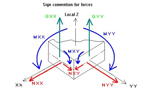
The following define the sign convention applied to forces for planar finite elements.

