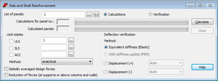
Select either the Theoretical (required) reinforcement layout located in the RC slabs design or Design > Required reinforcement of RC slabs/walls - options > Calculations to evaluate the reinforcement area for slabs or shells.
Only the Calculations option is active which may be performed using either the equivalent stiffness (elastic) or the stiffness update (inelastic) methods.
To access Verification option, select Analysis > Verification in the Slab - provided reinforcement layout.

The name of the code used for determining parameters of panel reinforcement type is displayed on the dialog title bar.
To begin calculations of slab or shell reinforcement, do the following.
- Limit states allows the definition of load cases taken into consideration during calculations for individual load cases in appropriate limit states (ULS, SLS and ALS - accidental state). SLS determines the code conditions for cracking (expressed in some codes by stresses or deformations) except deflections (Deflection verification field). Enter the appropriate load case numbers or click
 . In the Selection dialog box, select the load cases or load case combinations for particular limit states. If code combinations have been defined, then activating the relevant option in the Limit states field (
 ) determines the limit state for which the generated code combinations will be taken into account in calculations.
- Select panels that will be considered in calculations of the required reinforcement; Enter panel numbers or click
 and choose panels in the Selection dialog box
- Determine the method of calculating shell or slab reinforcement. The following calculation methods are available: analytical method, the method of equivalent moments (NEN), and Wood&Armer method of equivalent moments (see also: Method of calculating slab and shell reinforcement area).
Take note of two issues:
- Panel calculations are performed only for panels with numbers specified in the List of panels field and for cases or case combinations specified in the ULS, SLS, ACC fields.
- After modifying the parameters of a reinforcement set for a panel with calculated reinforcement, or a reinforcement parameter set for a panel, the reinforcement calculation results are out of date. Reinforcement calculation results are removed, whereas in the reinforcement result table, the table cells are presented in red (maps of reinforcement and panel cuts are inaccessible).
Under the panel list there are two calculation progress bars. The first indicates the current panel, while the other indicates all calculated panels. The bars are preceded by read only fields that show the number of the calculated panel and how many panels have been calculated, respectively.
The lower part of the dialog contains the following options.
- Globally averaged design forces. This option is available when the results of calculations of slabs and shells are discontinuous for the forces in nodes of finite element mesh. If four finite elements converge in one node, a different force value is determined for each element. If the Globally averaged design forces option is deselected, the results in nodes are averaged within a given panel for which reinforcement is being calculated. If the option is selected, the results in the nodes are averaged for all panels.
Note: If Globally averaged design forces is selected, you should be careful while calculating reinforcement for slab structures consisting of panels that are not located in one plane, for global averaging may result in the situation where quantities that do not correspond to each other are averaged for the edges of such panels.
- Reduction of forces (at supports or above columns and walls). When selected, values of moments and stresses in the vicinity of support points (or linear supports) are replaced with an average value obtained in the area near the supports/columns/walls (see Reduction of Values Near Supports).
If any errors occur during calculations, they will display in a prompt after completing the calculations.
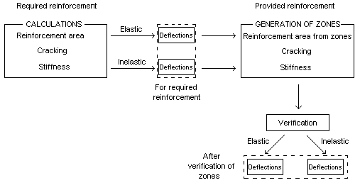
When reinforcement area, cracking, stiffness and deflection are calculated, verification of the reinforcement area from zones takes place. Verification is performed to obtain the final value of deflections. New areas are the basis for recalculation of cracking and stiffness values. See Methods of calculation of deflections in slabs / shells for more information on calculation algorithms of individual methods.
Verification (like calculations of required reinforcement) can be performed using either of the following methods.
- Equivalent stiffness (elastic).
- With stiffness update (inelastic).

Verification can be carried out for a freely-chosen combination or a combination component. In the SLS field, you can define an arbitrary load type such as simple cases, combinations, time history analysis, and so on. Select the Auto option to perform verification of a combination with the greatest elastic displacements for a given panel (arbitrary, selected from the Selection dialog). Choose a combination to be verified. It will include combinations from the SLS drop-down list.
See also:
Method of calculating slab and shell reinforcement area.
Data incoherence (calculation of slab and shell reinforcement).