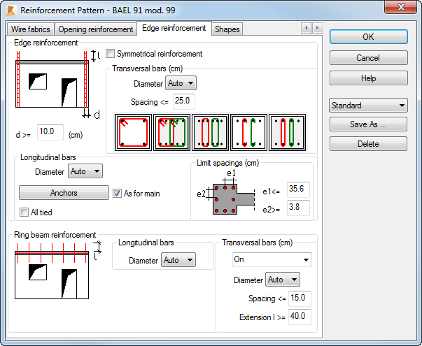
The Edge reinforcement tab allows you to define parameters of edge reinforcement.
Access
Select RC Design  Provided reinforcement layout, and then create a new RC element or open an existing one.
- Click Analysis Reinforcement Pattern.
- Click
 (Reinforcement Pattern).
Dialog elements
- For walls calculated according to the BAEL - simplified method
-
This reinforcement is a result of the generation of transversal bars that embrace main vertical bars (bars of distributed vertical reinforcement) over the following width.
- In walls subjected to a normal (non-seismic) load, the reinforcement near edges CV is generated in the hidden zone whose width equals the greater of the wall thickness or 20 cm
- In walls subjected to a seismic load, where the main reinforcement is not provided, the distributed reinforcement CV is generated in the hidden zone whose width equals the greater of the wall thickness and 20 cm.
- In walls subjected to a seismic load, where the main distributed reinforcement is provided, transversal reinforcement embraces the existing vertical bars over the width d'
- Simultaneously, conditions related to the minimal diameter and the maximum bar spacing are checked for bars positioned in the near-edge zone
- For walls calculated according to the classic method (BAEL) and according to ACI
-
This reinforcement is calculated for compression/bending. In the case of ACI, vertical reinforcement is distributed over the width of the boundary element defined on the layout for definition of geometry. Transversal reinforcement is generated according to the detailed requirements concerned with boundary zones. For BAEL, vertical and horizontal reinforcement is generated over the width d' (for non-seismic walls the value d' equals the greater value of the wall thickness and 20cm).
The following parameters of edge bars may be defined.
- For longitudinal bars it is possible to determine limit bar spacings (inactive for the BAEL simplified method), a required bar diameter, as well as to activate the All tied option. You can define a type of bar ends above the wall by selecting the relevant option in the Anchors dialog box
- For transversal bars it is possible to select a preferred arrangement of the transversal reinforcement as well as a required bar diameter and a preferred spacing.
- The d dimension refers to the width over which transversal bars (ACI) or longitudinal and transversal bars (BAEL) are generated. Simultaneously, code conditions are taken into account (the greater of the conditions is adopted).
Moreover, the BAEL classic method allows using the Symmetrical reinforcement option. This option is used to generate symmetrical reinforcement near edges (for maximal values of reinforcement and the width of hidden zones).
Reinforcement of horizontal ring beams CH is provided only in walls calculated according to the French BAEL code. It consists of longitudinal (horizontal) bars and transverse bars which are dowels connecting a ring beam with successive stories. The diameter of longitudinal bars as well as a diameter of transverse bars and their spacing can be defined on the Edge reinforcement tab. Default parameters correspond to the requirements of the minimum constructional reinforcement.
The Save As option allows you to reuse a set of reinforcement pattern parameters. This set is saved to your current user directory. You can reuse this set for the other element in the Reinforcement Pattern dialog or assign it to the selected element (or selected elements of the same type) in the RC Component Inspector.
The Delete option allows you to remove the selected set of reinforcement pattern parameters.