You can add crossings to profile views to identify where linear objects cross the profile relative to the parent alignment.
Use the Add Crossing To Profile View command to add crossings and labels to profile views for the following types of objects:
- Alignments
- Profiles
- Feature lines
- Survey figures
- 3D polylines
When you add crossings to a profile view, you specify which marker and label styles to apply to the crossings. You can set up unique styles for each type of crossing object so that you can display and label them differently.
Crossing alignments are shown as vertical lines in the profile view because they don't have levels, but you can specify a level value for the crossing alignment labels.

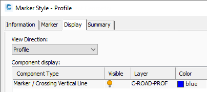
Marker styles are used to control the appearance of crossing objects in profile views. The appearance of the marker style is controlled on the Display tab of the Marker Style dialogue box. Select Profile from the View Direction list to review and edit how the marker style is configured for profile view. There is a single component which controls the display of both the marker (which is used for displaying crossing profiles, feature lines, survey figures and 3D polylines) and the crossing vertical line (which is used for displaying crossing alignments).

Crossing objects use profile view Crossing label styles.

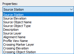
You can set up the label styles to include the following properties:

You can display the crossings and labels in the profile view using the level of the object, a surface, a profile, or you can manually specify a level. For alignments, the level option controls the level of the label as it appears in the profile view and it's specified manually.
Moving your cursor over a crossing in profile view to highlight it highlights the object in plan view. When reviewing the crossing properties on the Crossings tab of the Profile View Properties dialog box, selecting a crossing object in the dialog box highlights the object in plan view and profile view.