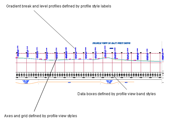
Use the profile view grid to display one or more profiles for a horizontal alignment.
When you create a profile view, you specify which existing profiles to display on the grid. Use these profiles as a reference for drawing new layout profiles on the grid.
A profile view can include one or more related profiles, along with multiple data boxes along the X-axis, above or below the grid. Data boxes annotate the profiles with chaining, level, horizontal geometry, and other data that assists engineering analysis.

Profile view displaying surface and layout profiles

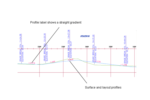
Closer view of surface and layout profiles
You typically use a profile view to display several profiles along a proposed route for a road, pipe, fence, or a similar structure. Use profile views to compare levels of several surfaces or design profiles along the alignment.
Within a profile view, you can superimpose the profile of another alignment. For example, in the profile view for a road, you can superimpose the profile of a culvert that occupies the same corridor. By superimposing a profile, you can analyze culvert levels in relation to the same alignment chainages used for the road surfaces.
A profile view can include projected objects from the drawing that you want to see in relation to a profile.
If you design a road, pipeline, or a similar structure across the landscape, and you want to compare the feasibility of several possible routes, a profile view of each route can help with the comparison.
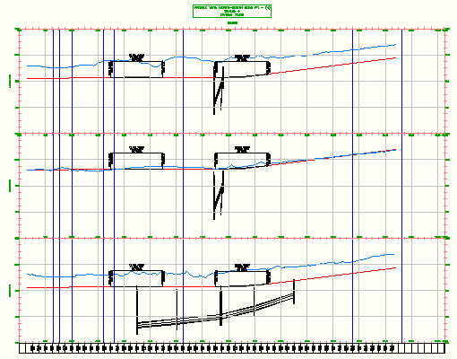
Autodesk Civil 3D allows profiles to split to fit within a specified profile view height and displayed in either single or multiple profile views.
Creating Profile Views
You can create profiles without displaying them on a profile view. When you create a profile view, you can display any of the profiles created from a selected alignment. You can configure data boxes and profile annotations in a profile view to make it clearer or more informative for the user.
An easy-to-use wizard guides you through the process of creating single, multiple, or associated longitudinal section views. In the process, you can specify whether to display pipe networks and hatch areas to show cut and fill regions.
- A single profile view is typically used to design and edit a profile. It displays the specified chainage range of the corresponding alignment in a single profile view grid.

- Multiple profile views are useful for plotting shorter segments of a profile in individual profile view grids of a consistent length and vertical scale.

Use multiple profile views to create final construction documents from a design. For best results, design your profile in a single profile view, and then create multiple profile views for plotting.
- Associated longitudinal section views are a collection of related profiles drawn in separate, vertically arranged profile views. Typically a centerline profile is contained in one profile view, and its left and right offsets are drawn in profile views that are placed above and below the centerline profile view.

A profile can be split within either a single or multiple profile view. This allows a profile view to display a profile level range that is greater than the specified height of the profile view.
