Use this tool to calculate sight distances along a carriageway and to ensure that the design meets the required minimum sight distances.
Graphic elements are added to the drawing to indicate the locations where the design meets or does not meet the required minimum sight distance, and a report can be generated which lists the sight distance status at each station.

Changes to the Check Sight Distance Command
Changes have been made in Autodesk Civil 3D 2014 SP1 and Autodesk Civil 3D 2015 to the Check Sight Distance command. The manner in which the actual sight distance is calculated (as reported in the sight distance report) has changed, and the graphics created in the drawing to illustrate the sight distance features have changed.
Previous Behavior
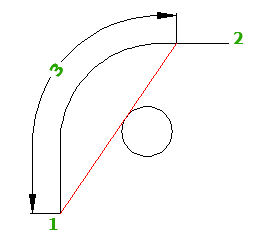
In previous versions of the application, when an obstruction was encountered, the command reported the actual sight distance ("3" in the illustration below) as the distance between the eye ("1" in the illustration below) and the obstruction, using the line of sight between the eye and the target ("2" in the illustration below).
A visible sight line (shown in green below) was drawn from the eye to the obstruction, and an obstructed sight line (shown in red below) was drawn starting where the obstruction began and ending at the target point.

Current Behavior
Now when an obstruction is encountered, the command reports the actual sight distance ("3" in the illustration below) as the distance along the alignment between the eye ("1" in the illustration below) and the furthest point of visibility along the alignment towards the target (the target is "2" in the illustration below).
When an obstruction is encountered, the obstructed sight lines are now drawn in the manner shown below.

-
Click


 Find.
Find.
- On the Sight Distance Check - General page, specify the path along which you want to check. Note: To enable the Next and Finish buttons you must specify a valid sight path.
- Select a surface to perform the check against and click
 to add it to the list. The surfaces are listed in the order of priority. If there are multiple surfaces at a given location, then the check is done against the surface with the highest priority. You can change the priority by clicking the
  and
and  arrows.
 - Click Next.
- On the Sight Distance Check - Sight Distance page, enter values for the following:
- Minimum Sight Distance
- Eye Height
- Eye Offset
- Target Height
- Target Offset
- Click Next.
- On the Sight Distance Check - Results page, select the sight distance graphic components that you want drawn in the model. You can hover over a component in the list to see a preview.
- Click
 to select a hatch color for the display of the obstructed areas.
 - Optionally, create a sight analysis report. From the Choose A File Type list, specify one of the following report style sheets:
- ReportCSV
- ReportHTML
- ReportTXT
- ReportXML
- Specify the location to save the report. Click Finish.