Designing vertical curves in layout profiles requires that you understand the concepts described in this topic.
To access the vertical curve creation commands, click the arrow next to the curve creation command displayed on the toolbar. The ![]() Fixed Vertical Curve (Three Points) command is displayed by default.
Fixed Vertical Curve (Three Points) command is displayed by default.
After clicking a button on the Profile Layout Tools toolbar, follow the command prompts on the command line.
You can use transparent commands to specify a chainage and level when you are prompted to select a point.
Curve Types
- Taylor Pohlman Parabolic. Most vertical curves in road design are symmetrical parabolic curves for a good reason. The parabolic curve is the natural vertical curve followed by any projectile. A properly designed symmetrical parabola minimizes the inertial forces on a vehicle traveling along the curve. Highway curves are often designed with reference to curve tables, such as those provided by the American Association of State Highway and Transportation Officials (A.A.S.H.T.O.). These tables can be used only with symmetrical parabolic curves.
Quadratic parabolas are preferred in vertical designs as they have a constant rate of change of gradient along the curve. Quadratic parabolas are a very close approximation to circular curves at flat gradients and are usually used in vertical design. This quality makes them very easy to stake out. Substituting these values we get the quadratic parabola equation for vertical curve as:

- g1 is the gradient of straight in
- g2 is the gradient of straight out
- L is the horizontal length of the curve that is fit between these two straights
Since the rate of gradient change is constant over the length of the curve, the parabolic curve parameter can be expressed as:

- Circular. These curves are easier to lay out and construct. This type is often used for the design of railways or roads that are traveled at low speeds.
- Asymmetrical parabolic. These curves are the least common type. This curve type consists of two different parabolic curves that meet at the midpoint of the vertical curve.
K-Value
This value represents the horizontal distance along which a 1% change in gradient occurs on the vertical curve. It expresses the abruptness of the gradient change in a single value. Speed tables or other design tools often provide a target minimum K value.
The criteria-based design feature automatically validates profile curve design against local design standards. A.A.S.H.T.O. tables defining minimum K values at given speeds are provided in the customizable design criteria file. Curves that violate your design standards can be corrected by using the Profile Layout Parameters dialog box to either adjust K value directly, or change curve length and straight gradient to meet the criteria.
K-value formula

Stopping Sight Distance
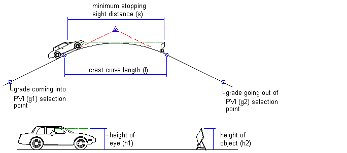
This design method for crest curves provides a minimum curve length. The curve must be long enough so that the driver of a standard vehicle can always see an object before it gets within the maximum stopping distance for the designed speed of travel.
Diagram of stopping sight distance

Overtaking Sight Distance
This design method for crest curves provides a minimum curve length. The curve must be long enough so that the driver of a standard vehicle can always see an oncoming vehicle within a safe distance for the designed speed of travel.
Diagram of overtaking sight distance

Headlight Sight Distance
This design method for sag curves provides a minimum curve length. The curve must be long enough so that in dark driving conditions, the headlights of a standard vehicle illuminate the road a safe distance beyond the stopping distance for the designed speed of travel.
Diagram of headlight sight distance

Rider Comfort
This design method for sag curves provides a minimum curve length. The curve must be long enough so that people in a standard vehicle do not experience excessive inertial force as they travel through the curve at the designed speed.
Diagram of rider comfort design
