This example demonstrates how to use the Vertex Color green channel to control opacity.
Like the example on the page Using Component Swizzle to Provide Different Vertex Color Channels, it assumes you have a model with vertex colors. For these steps, we used the dinosaur with green vertices.

- If you use the scene from the previous example, delete the wire that connects the VertexColor0 node to the Standard Base node
 Base Color input.
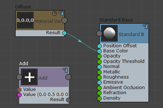
- Create a custom Interactive shader, and add a color or a map as the Standard Base
 Base Color input.
- Use the Material Editor to assign a color that has no Green component.
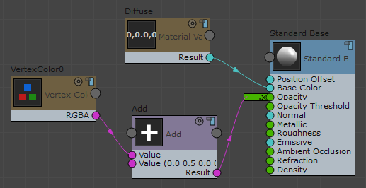
- Add a Math
 Add node. Click its second Value input and change the default string to
0 0.5 0 0.

- Add a Vertex Inputs
 Vertex Color 0 node to the graph, and wire it to the other,
first Value input of the Add node.
- Wire the Result output of the Add node to the Opacity input of the Standard Base Node.

In Shaded and Realistic viewports, the dinosaur turns dark.
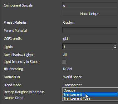
- Click the Opacity input channel on the Standard Base node. On the Properties panel, change the Component Swizzle value to
g.
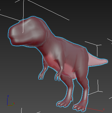
In viewports, the dinosaur reappears.

- On the Properties panel, change the Blend Mode from Opaque to Transparent.

The 0.5 value added to the green vertex color channel causes all areas with green to be less transparent than the rest of the creature.
This effect is easiest to see in Shaded viewports.
