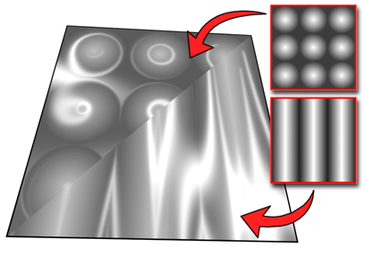
You can use a bitmap file or procedural map to control the Orientation material component. Orientation controls the position of the anisotropic highlight. Using an Orientation map changes the highlight's position.
Black and white values in the map have little effect, but maps with a high percentage of grayscale values, such as Noise or Falloff, can be very effective. You can also achieve effective results using the same map for Orientation and Bump values.

Using anisotropy orientation
Reducing the Amount value of the Orientation map on the Maps rollout reduces the map's effect, thus increasing the effect of the Orientation value on the Basic Parameters rollout. When Amount is 0 percent, the map isn't used at all.
The effect of an Orientation map, like Anisotropy, is not very apparent unless Specular Level is fairly high and Glossiness is fairly low.
Procedures
To use an Orientation map:
- Click the Map button for Orientation.
3ds Max opens the Material/Map Browser.
- Choose from the list of map types, and then click OK.
(If you choose Bitmap as the map type, 3ds Max opens a file dialog that lets you choose the image file.)
- Use the map controls to set up the map.
Alternatively, you can use the ![]() Slate Material Editor to wire a map node to the Orientation (or Anisotropy Angle) component.
Slate Material Editor to wire a map node to the Orientation (or Anisotropy Angle) component.