Lets you create parametric Swept Objects.
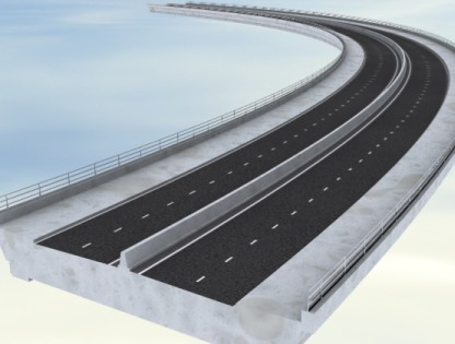
You can use swept objects in many ways, but most often they are for creating objects that parallel roads or railways: features such as bridges, tunnels, embankments, and ditches.
Parent shapes provide a path for the swept object, which can have one or more parent shapes. Multiple parent shapes let you create of additional spanning and closing surfaces to span the gap between parent shapes.
A swept object definition can be saved to a text-based Swept Object Style (SOS). Each style contains a set of elements. Each element represents a single surface within the swept object. Each element features adjustable (and variable) horizontal and vertical offsets and an independent material channel definition. By default, swept objects use the CivilViewSurfaces material.
Interface
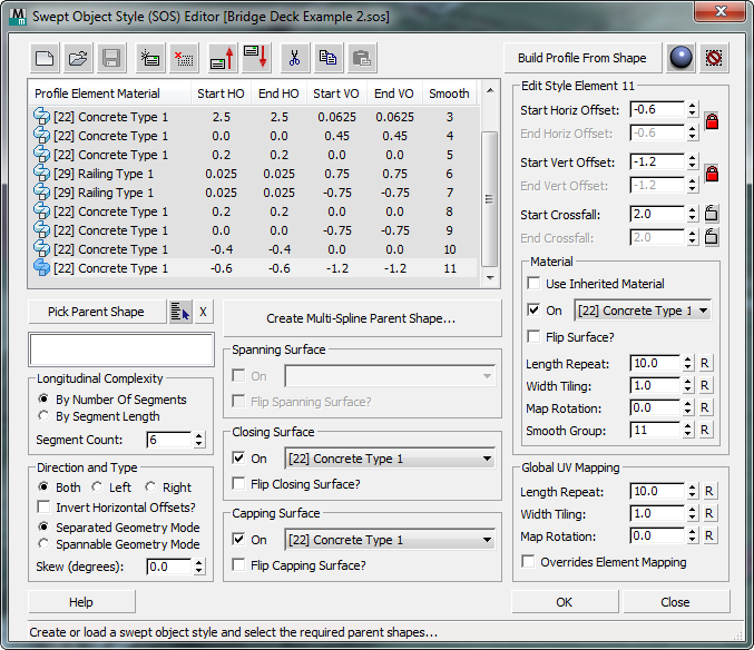
[SOS element list]
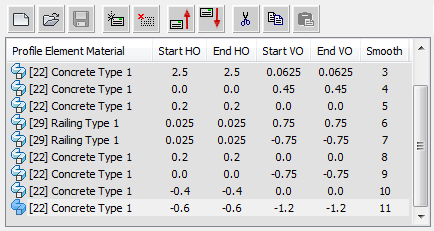
Lists the contents of the current swept object style. Each line shows an individual element in the list. Highlighting an element displays its details in the remaining controls on the editor.
-
 Start New Style
 - Click to create a new Swept Object Style.
-
 Open Style
 - Click to open a previously created Swept Object Style.
-
 Save Style
 - Click to save the current Swept Object Style.
-
 Add new element
 - Click to add a new element to the current Swept Object Style.
-
 Delete selected element
 - Click to delete the selected element from the current Swept Object Style.
-
 Move selected element up
 - Click to move the selected element up by one position in the element list.
-
 Move selected element down
 - Click to move the selected element down by one position in the element list.
-
 Cut Element
 - Click to cut the selected element from the style, saving it to the Clipboard.
-
 Copy Element
 - Click to copy the selected element and save it to the Clipboard.
-
 Paste Element
 - Click to paste a cut or copied element.
You can paste a Cut element to a different location in the current style, and you can paste a Cut or Copied element to a different SOS.
- Build Profile From Shape
- To base a swept object style on one that is already present in the scene, click this button to turn it on, then click in a viewport to select a shape. Civil View creates a new SOS with the same parameters as the one associated with the shape, provided the shape you click has an SOS.
This feature is particularly useful if cross-section drawings already exist of the object that you are creating. In this case, an existing polyline from the cross section drawing can be imported into the swept object style in order to form the basis of the profile.
If the selected shape object contains material ID assignments at the segment level, these are also carried across into the resulting swept object style.
-
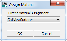
 Change Material Assignment
 - Click to display a dialog that lets you change the material assigned to swept objects.
-
 Reset Swept Object
 - Click to delete the swept object you are currently creating in this SOS Editor session.
- Pick Parent Shape
- Click to turn on, then click in a viewport to select a parent shape.

-
 [pick by name] Click to open a dialog (similar to Select Objects) that lets you pick shapes by name.
 - "X" button Click to remove the parent shape.
-
- Create Multi-Spline Parent Shape
- Click to open a Build New Parent Shape dialog that lets you construct a parent shape that includes more than one spline.
Swept Object Styles can be applied to either single or multiple shapes. Each parent shape can consist of one or more splines. If a swept object style is applied to multiple parent shapes, parameter instancing is automatically applied to help make sure that a single set of parameters is shared across all resulting swept objects.
- [parent shape list]
- Displays the names of the parent shapes you have chosen.
Longitudinal Complexity group
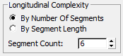
- By Number Of Segments (The default.) Adjust complexity using the number of segments in the parent shape.
- By Segment Length Adjust complexity using the length of segments in the parent shape.
- Segment Count
-
Affects the complexity of the resulting swept object. Higher values result in more complex object geometry.
It is best to use the lowest possible value in this spinner, but the precise value to be used depends on the geometry of the parent shapes.
Direction and Type group
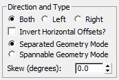
- Both (The default.) The profile extends in both directions.
- Left The profile extends only to the left.
-
Right The profile extends only to the right.
If you choose either Left or Right, the Spanning, Closing, and Capping Surface controls are disabled.
- Invert Horizontal Offsets?
-
When on, reverses the direction of all horizontal offsets in the swept object profile. Default=off.
-
Separated Geometry Mode (The default.) Creates identical, non-spanning geometry along each spline in the parent object.
This choice is useful for creating walls and noise barrier profiles, where potential gaps between splines represent gaps in the wall or barrier.
-
Spannable Geometry Mode Creates spanning and closing surfaces between the original splines and the tail ends of the swept profile.
This choice is useful for creating bridge decks that need to span a gap between two or more splines in a parent shape.
- Skew (degrees)
- When set to a nonzero value, skews the swept object profiles. Default=0.0.
When equal to 0.0, profiles are offset at a normal from the direction of the parent shape. Nonzero values are useful for objects such as asymmetrical bridge decks.
Spanning Surface group
A spanning surface is an optional surface "draped" across the gap between the parent splines. This can be useful for creating an asphalt surface over a bridge deck.
Not available if you have chosen Left or Right in the Profile Direction And Type group (see above).
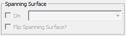
- On
- When on, builds the spanning surface.
- [sub-material drop-down list]
- Chooses a material channel for the spanning surface.
- Flip Spanning Surface?
- When on, flips the surface normals of the spanning surface.
Closing Surface group
A closing surface is an optional surface "draped" across the gap between the final surfaces of the swept object. This is useful for creating the underside of a bridge deck.
Available only if there is more than one parent shape, and the parent shapes are arranged in a way that permits Civil View to construct the closing surface. See Build New Parent Shape Dialog.
Not available if you have chosen Left or Right in the Profile Direction And Type group (see above).
Not available if the chosen construction method is Separated Geometry Mode (see above).
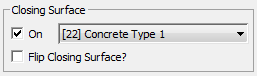
- On
- When on, builds the closing surface.
- [sub-material drop-down list]
- Chooses a material channel for the closing surface.
- Flip Spanning Surface?
- When on, flips the surface normals of the closing surface.
Capping Surface group
A capping surface closes or caps the open ends of the swept object.
Not available if you have chosen Left or Right in the Profile Direction And Type group (see above).
Not available if the chosen construction method is Separated Spline Geometry (see above).
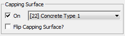
- On
- When on, builds the capping surface.
- [sub-material drop-down list]
- Chooses a material channel for the capping surface.
- Flip Spanning Surface?
- When on, flips the surface normals of the capping surface.
Edit Style Element group
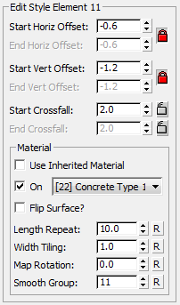
Edits the settings of the element currently highlighted in the SOS element list. Each element represents a single surface in the swept object, and features a horizontal and vertical offset, along with an independent material channel selection.
- Start Horiz[ontal] Offset / End Horiz[ontal] Offset
- Adjust the horizontal offset of the SOS element.
-
 Lock Start and End Horizontal Offsets Click to lock or unlock the Start and End values. When values are unlocked, the horizontal offset can vary along the length of the swept object. Default = locked.
-
- Start Vert[ical] Offset / End Vert[ical] Offset
- Adjust the vertical offset of the SOS element.
-
Lock Start and End Vertical Offsets Click to lock or unlock the Start and End values. When values are unlocked, the vertical offset can vary along the length of the swept object. Default = locked.
-
- Start Crossfall / End Crossfall
- Adjust the crossfall of the swept object.
-
 [lock Start/End Crossfall] Click to lock or unlock the Start and End values. When the Start Crossfall or End Crossfall value is locked, changing the Vertical Offset does not affect this value; otherwise, it does. Default = unlocked. Note: End Crossfall is unavailable unless you have unlocked the Horizontal or Vertical Offset values.
-
Material group
- Use Inherited Material
- When on, the material from the preceding profile element is applied to this element, along with the preceding element's mapping parameters.
Turning this on disables the other settings in the Material group, except for Smoothing Group.
- On
- When off, no material is applied to the element, making it a gap element. Default=on.
Gap elements create an invisible offset between the parent shape and the first surface in the swept object. Gap elements are displayed as "[Gap]" in the Swept Object Style element list.
- [sub-material drop-down list]
- Chooses a material channel for the swept object element. Swept elements use the CivilViewSurfaces material.
- Flip Surface?
- When on, flips the surface normals of the element.
- Length Repeat
-
Sets the distance over which the selected material is repeated along the element. Default = 10.0 world units.
This option is valid only for tileable texture maps, and is ignored when used with procedural texture maps.
- Width Tiling
-
Sets the number of times the selected material is repeated across the width of the element. Default = 1.
This option is valid only for tileable texture maps, and is ignored when used with procedural texture maps.
- Map Rotation
-
Sets a rotation to apply to mapping on the element.
This option is valid only for tileable texture maps, and is ignored when used with procedural texture maps.
- Smooth[ing] Group
-
Sets the smoothing group ID used by the element. By default, the smoothing group is incremented by one when you add a new element to the profile.
- Adjacent elements that use differing smoothing group IDs do not have surface smoothing applied.
- Adjacent elements that use common smoothing group IDs are smoothed to create the illusion of a curved swept object profile.
Valid smoothing group IDs are values between 1 and 32. A value of 0 can also be specified: This prevents any longitudinal smoothing to be applied to any single profile element.
- "R" buttons
- For each of the previous controls, click "R" to reset the value to its default.
Global UV Mapping group

These settings affect material mapping on spanning surfaces and closing surfaces.
Length Repeat, Width Repeat, and Map Rotation behave as they do for elements.
- "R" button Click to reset the control to its original value.
- Overrides Element Mapping
- When on, the global UV mapping settings affect the element, and override the mapping parameters stored at the profile element level. Default=off.