Lets you associate objects from the Civil View Object Libraries with imported shapes such as strings or feature lines.
This feature works in association with the Civil View Geometry Import Panels. Feature Interpretation can be activated from these panels, and direct access to this panel is provided in order to edit these styles.
Interface
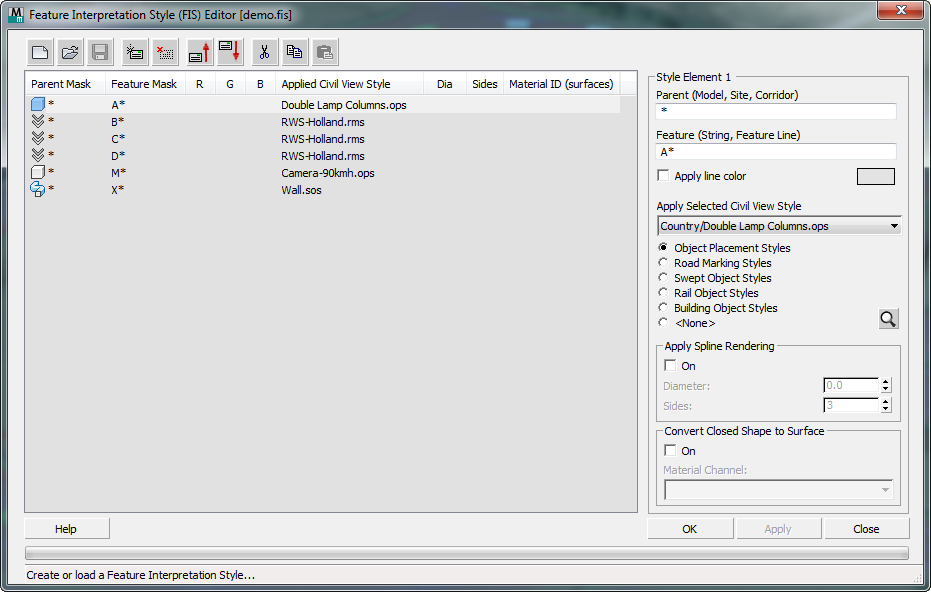
[FIS element list]
Lists the contents of the current FIS style. Each line shows an individual element. You can select an element to display its settings in the FIS Element group.
-
 Start New Style
 - Click to create a new Feature Interpretation Style.
-
 Open Style
 - Click to open a previously created Feature Interpretation Style.
-
 Save Style
 - Click to save the current Feature Interpretation Style.
-
 Add new element
 - Click to add a new element to the Feature Interpretation Style.
-
 Delete selected element
 - This button removes the selected element from the current Feature Interpretation Style.
-
 Move selected element up
 - This button moves the selected element up by one position in the current Feature Interpretation Style.
-
 Move selected element down
 - This button moves the selected element down by one position in the current Feature Interpretation Style.
-
 Cut Element
 - Click to cut the selected element. The element remains on the clipboard.
-
 Copy Element
 - Click to copy the selected element to the clipboard.
-
 Paste Element
 - Click to paste the cut or copied element to another position in the current style or to an alternative style definition.
FIS Element group

Displays the settings associated with the FIS element selected in the list.
Each style element includes masks for the parent and feature. These let you apply a Civil View style definition to that particular imported feature.
You can also set the line color for imported shapes.
- Parent (Model, Site Corridor)
- Specifies a full or partial mask (wildcard string) for the originating civil design parent label. The Civil View style is applied to all features in the current import session that match this feature mask. Valid wildcard masking examples are as follows:
- DWM*
- CORRIDOR NUMBER?
- LAYER 1
- ???MODEL*
- *DESIGN
Examples of originating parent references include MX Models, Civil 3D Corridors and Sites, AutoCAD Layers, and Microstation Levels.
- Feature (String, Feature Line)
- Specifies a full or partial originating mask (wildcard string) for the originating feature. The Civil View style is applied to all features in the current import session that match this feature mask. Valid wildcard masking examples are as follows:
- M*
- AC1?
- C20
- ?C*
- *1
Examples of originating feature name references include MX Strings, Civil 3D Feature Lines, and Breaklines.
- Apply Line Color
- Specifies the color to apply to all imported features that match the feature mask.
If you turn off this option, Civil View applies a hard-coded default line color. Line colors affect only the display of shapes in 3ds Max viewports; they have no effect on rendered output.
- Apply Selected Civil View Style drop-down list
- Chooses a predefined Civil View style. The radio buttons below the drop-down list indicate the style type you have chosen.
The list contents are derived from folders in the Civil View Country, Project, and Private Resource Kits. If a style with the same name exists in more than one active resource kit, Civil View matches the first matching style name found in any resource kit in the following order of priority:
- Private
- Project
- Country
- [style type radio buttons]
- Show the type of predefined Civil View style that will be applied to imported strings that match the label mask. If you do not wish to apply a style but still wish to set the line color of these strings, choose None.
Changing this selection changes the list of available styles.
-
 [style preview]
 - Click to open a small Style Editor window that shows the contents of the selected style.
You can also view this window by double clicking an element in the main FIS Style list.
- Apply Spline Rendering
-
By default, imported shape objects are not renderable in a 3ds Max scene. You must create additional geometry along the path of an imported shape (such as road markings or guard rails) in order to see the path of the shape in rendered views.
However, there are occasions when it can be useful to render the shape object itself; for example, when imported shape data represents the cables of a suspended bridge deck. These controls let you make shapes renderable.
- On When on, 3ds Max renders shapes in the current style.
- Diameter Sets the diameter of the renderable geometry.
- Sides Sets the number of sides of the renderable geometry.
- Convert Closed Shape to Surface
- When triangulation data is not available, this option provides an alternative by automatically generating surface geometry.
When you turn on this option, incoming closed shapes that match a specified feature mask are triangulated automatically. You can also assign a material channel so the surface has the correct texture applied.
This option is particularly useful with some types of survey data where boundaries between different surface types are represented by a series of boundary strings.
Note: This feature has no effect on shapes that match the feature mask but do not form a closed boundary.- On Turn on to enable closed shape conversion.
- Material Channel drop-down list Chooses a material channel from the CivilViewSurfaces material to apply to the generated surface.