Start working with OpenSubdiv:
- Create or load a model to apply smoothing to.
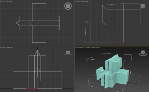
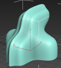
For best results, the model should have relatively sharp angles (90 degrees or less) that respond well to the smoothing effect. The following illustration shows a qualifying example:
- Apply the OpenSubdiv modifier to the model.
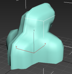
With the default Iterations value of 1, the smoothing is now apparent, as is its low resolution. In assessing the modifier's effect, it also helps to view the mesh subdivision.
- Activate a shaded viewport, and if the Edged Faces switch is off, press
F4 to activate Edged Faces.
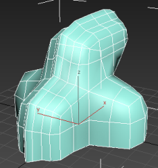
At the first iteration, each quadrilateral polygon in the original object is subdivided into four polys.
To improve the smoothing quality, increase the Iterations value.
- Turn off Edged Faces, then on the General Controls rollout of the OpenSubdiv modifier, click the up arrow of the Iterations spinner to increase the value to 2.
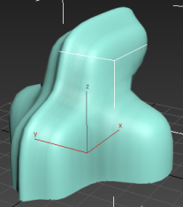
The model's surface becomes noticeably smoother, as the mesh topology is increasingly subdivided.
- Continue incrementing the Iterations value until you reach 5.
If you turn on Edged Faces again at this point, you can see that the model is highly and uniformly subdivided. With large, complex models, the increased mesh resolution can slow down viewport interaction. If that happens, and you have a sufficiently powerful display card installed, you can switch the Operating Mode setting to GPU Display. This offloads geometry processing to the graphics card, which can greatly improve viewport feedback.
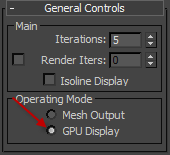
In general, an Iterations value of 5 provides sufficient smoothing for objects that require minimal or no creasing. By default, it applies to smoothing both in the viewports and when rendering.
If you need even more smoothing, you can set a separate value for Render Iterations. Its affect shows up only in rendered output. We'll cover this in the following task.
Apply creasing via the Editable Poly settings:
- Delete the OpenSubdiv modifier from the object. If the model's base level is not Editable Poly, or the Edit Poly modifier isn't applied, convert it to an editable poly object.
This provides access to the Crease settings at the Vertex and Edge sub-object levels.
- Reapply the OpenSubdiv modifier; keep the default Iterations value of 1.
- In the modifier stack, access the Edge sub-object level of the Editable Poly entry, and turn off the Show End Result On/Off Toggle.
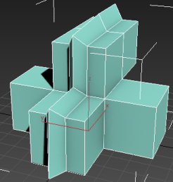
The base, unsmoothed geometry is now visible in the viewports. This makes it easier to select edges for creasing.
- Select edges where creasing should occur.
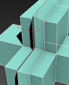 Tip: The greater the angle between the adjacent polygons, the more evident the results of edge creasing will be. Thus, applying creasing to edges between coplanar polygons (that is, within flat surfaces) has practically no effect.
 - Turn Show End Result back on, then on the Edit Edges rollout, increase the Crease value.
As you adjust the setting, the sharpness of the crease increases slightly in shaded viewports.
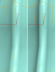
Left: Crease=0.0; Right: Crease=0.5
Note: OpenSubdiv does not support the Weight setting for edges and vertices in editable poly objects.However, to get distinct creasing, you might need to increase the Iterations value. This increases the degree of subdivision, providing better mesh resolution for supporting visible creasing.
- On the modifier stack, access the OpenSubdiv entry, then on the General Controls rollout, click the up arrow on the Iterations spinner once, to change Iterations to 2. Note the difference, then continue clicking slowly until you reach 5. Notice what happens to the crease each time you click.
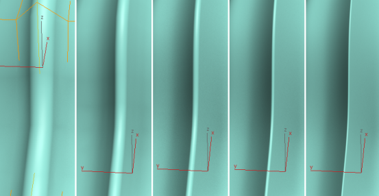
In the following illustration, Crease is set to 0.5, and Iterations increases from 1 to 5, from left to right.
The maximum value permitted with the OpenSubdiv modifier's Iterations setting is 6, which typically supports Crease values of up to 0.5 or so. If you need sharper creasing, you can obtain it as follows:
- At the Edge level of the editable poly object, increase the Crease value. Then, in the OpenSubdiv modifier, turn on Render Iters and set it to a higher value, such as
7. Render the image.

Crease=0.7; Render Iterations=7
This procedure continues from the preceding one. In it, you'll set up creasing at the Editable Poly level. The OpenSubdiv modifier recognizes these settings and uses them to add sharp edges to the smoothed surface.
Create crease sets with the CreaseSet modifier:
- Continuing from the preceding procedure, delete the OpenSubdiv modifier. Don't deselect the edges, though.
- Apply the CreaseSet modifier and then apply the OpenSubdiv modifier.
Important: The OpenSubdiv modifier should always be above the CreaseSet modifier in the stack.
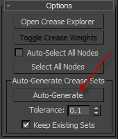
- Access the CreaseSet modifier in the stack, then expand the Options rollout and, in the Auto-Generate Crease Sets group, click the Auto-Generate button, then click the Yes button on the confirmation dialog that opens.
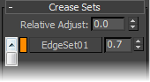
A new entry appears on the Crease Sets rollout. Its name is EdgeSet01, and the displayed Crease value is the same one you assigned the edges previously.
This happened because you already had edges with Crease values at the Editable Poly level of the stack. The edges need not be selected for Auto-Generate to work. Clicking Auto-Generate results in a new Crease Sets entry for each set of edges with the same Crease value, and also for each set of vertices with the same Crease value. You'll explore this in the next step.
Tip: If you're not sure which sub-objects belong to a crease set, right-click its entry in the list and choose Select Elements In Set. You can also edit the set contents, for example, by selecting some additional sub-objects, right-clicking the set's list entry, and choosing Add Selection To Set. - Go to the Editable Poly level of the modifier stack, and access the Edge sub-object level if necessary.
- Select several new edges and assign a different Crease value.
- Access the Vertex level, select some vertices, and assign them any Crease value.
- Go to the CreaseSet stack level and click Auto-Generate again.
The Crease Sets rollout list now shows all the sets you've created.
You can also create crease sets within the CreaseSet modifier, as you'll see in the following task:
In the preceding procedure, you created a single set of crease edges. That is, you assigned the same Crease value to multiple edges in a model. But what if you want to assign different Crease values to different sets of edges? It's possible to do this manually, but the CreaseSet modifier makes it easy to manage multiple crease sets and more.
Create a crease set entirely within the CreaseSet modifier:
- In the modifier stack, expand the CreaseSet entry and click either Vertex or Edge.
Note: These sub-object levels refer to the original geometry, not the subdivided object. When the CreaseSet modifier is active, you can see the original geometry as a wireframe cage enclosing the subdivided object.
- Select some sub-objects and click the Create Set button under the Crease Sets list.
Tip: You can select an edge loop by double-clicking an edge, and an edge ring by selecting an edge and then Shift+clicking another edge in the same ring.
The new set appears in the list, with a default name and Crease value. You'll learn about changing Crease values in the next procedure; to learn about changing set names, read on.
Note: If any of the sub-objects you selected already belong to an existing set, they are automatically removed from that set when you create the new set. Each edge and vertex can belong to only one crease set. - To change a set name, right-click its list entry and choose Rename, then use the dialog that opens to edit the name and click OK.
You can also specify a name for the next set you create:
- Edit the contents of the text field next to the Create Set button, then select some vertices or edges and click Create Set.
The new set appears in the list with the name you gave it plus an appended number.
An important aspect of the CreaseSet modifier, hinted at earlier in this task, is that a sub-object can belong to only one set at a time:
- Select some sub-objects and create a set.
- Without changing anything, click Create Set again.
The new set appears in the list, while the older set's name is now enclosed in square brackets (for example, "[CornerVerts]"). The brackets indicate that the set is empty, as you can easily prove by right-clicking its name and choosing Select Elements in Set. This results in all sub-objects being deselected.
This procedure continues from the preceding one.
Adjust creasing with the CreaseSet modifier:
- Select an object with the CreaseSet modifier applied, and activate the CreaseSet modifier.
- If necessary, create some crease sets.
- To modify a single set's Crease value, edit the value in the numeric field to the right of the set's name.
- To modify multiple sets' Crease values, first select all the sets to modify. The background color of a selected set is blue. Then enter the amount by which the selected Crease values should change in the Relative Adjust field. After you do so, the Relative Adjust value (whether positive or negative) is added to the Crease value of all selected sets.
The CreaseSet modifier lets you adjust Crease values directly, one at a time, and en masse in relative terms:
Using Multiple Objects with CreaseSet
The CreaseSet modifier is designed to manage creases in multiple objects simultaneously, which can help speed up editing of geometry in scenes that contain large amounts of data.
Adjust creasing in multiple objects simultaneously:
- Create a scene containing multiple non-instanced copies of one or more objects.
For example, the scene might contain several copies of a truck. Because they're copies, rather than instances, you can introduce small modeling differences that serve to distinguish the vehicles from each other.
- Select all copies of objects that will be subject to creasing and OpenSubdiv.
- Apply the CreaseSet modifier.
This applies an instanced copy of the modifier to each object.
- Apply the OpenSubdiv modifier to each object.
Tip: If you want to use different smoothing values with each object, apply OpenSubdiv to each separately. Otherwise, apply an instanced version, as with CreaseSet.
- Select all of the objects, then go to the Edge or Vertex sub-object level of the CreaseSet modifier and select sub-objects that will all get the same Crease values.
For instance, you might select edges of raised areas on the hood of each truck.
- Name the set and click Create Set.
- Set a Crease value for the set. All of the designated areas receive the changed value.