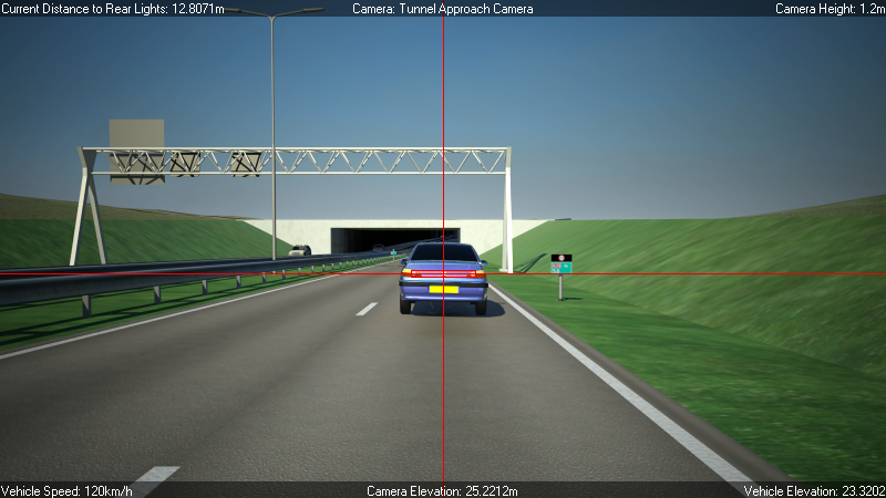
The Sight Checker tool sets up a rendering effect that can display analytical sight-distance information when you render your scene.
The Sight Checker sets up a simple visual check of sight lines on highways. This is done by tracking and analyzing the position and distance from the current viewpoint to one or more target objects, after each frame of an animation is rendered. All reported distances are calculated as straight line distances.
The tool includes the following features:
- Target objects can be one or more geometric objects in the current 3ds Max scene.
- Each rendered frame is analyzed by searching for pixels that display geometry from the nominated target objects. These target pixels are then gathered for further analysis.
- The distance to the underlying geometry under each target pixel is recorded. The nearest, average, and farthest of these distances is then stored.
- Once this information has been gathered, any of the following displays can be superimposed on the frame:
- A target box around the extents of the target objects.
- Cross hairs through the center of the extents of the target objects.
- Analysis data at the top or bottom of the frame.
This information can include a range of different parameters, such as actual target distance, camera location, parent shape name, camera name, and so on.
Additionally, information that does not relate to the sight distance test can also be displayed, such as the name of the computer that rendered the frame, the name of the person that rendered the frame, the name and path of the 3ds Max file, and the date and time that the frame was rendered.
- A watermark, such as a company or project logo.
Sight Analysis Data File
You can also send the analysis data to a text file, for further analysis by tools other than 3ds Max. The file contains one line of information per frame. Data items are delimited by semicolons, using the following format:
- Field 1: Frame Number
- Field 2: Number of pixels on which target object(s) were detected
- Field 3: Near distance to target object(s)
- Field 4: Far distance to target object(s)
- Field 5: Mid distance to target object(s)
- Field 6: Percentage of pixels on which target object(s) were detected
- Field 7: Camera Station
- Field 8: Camera Horizontal Offset from Parent Shape
- Field 9: Camera Vertical Offset from Parent Shape
- Field 10: Camera Elevation
- Field 11: Camera Parent Shape Name
Here is an example of an output file:
0;5309;-173.529922;-182.001648;-177.765778;1.728190;50.9163;6.93265;1.561;1.561;Line01
2;5480;-170.633743;-178.974899;-174.804321;1.783854;53.8326;6.93265;1.561;1.561;Line01
4;5641;-167.737015;-176.033371;-171.885193;1.836263;48.0;6.93265;1.561;1.561;Line01
Interface
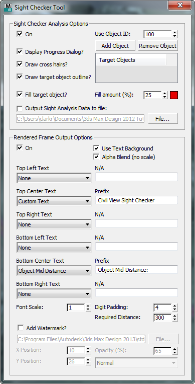
Sight Checker Analysis Options group
This part of the dialog controls the process of analyzing the rendered frame for object and distance information.
- On
- When on, the Sight Checker Analysis render effect is active.
- Use Object ID
- Specifies the object ID used by the target objects. Default = 100.
In 3ds Max, any object that is assigned a nonzero Object ID receives the rendering effect associated with that channel ID. In this case, sight-distance analysis is carried out for all objects that have this ID.
- Add Object
- To add a target object, click to turn on, then click an object in a viewport. Civil View assigns the Object ID to this target.
- Remove Object
- To remove a target object, highlight it in the list, then click this button. Civil view sets the object's ID to 0.
- Target Objects list
- Lists the targets you have chosen.
- Display Progress Dialog?
- When on, displays a progress dialog while the frame is being analyzed.
- Display cross hairs?
- When on, cross hairs are drawn over the rendered frame to indicate the center of the group of pixels that represent a target object.
- Draw target object outline?
- When on, a box is drawn over the rendered frame around the group of pixels that represent a target object.
- Fill target object?
- When on, draws a color over the group of pixels that represent a target object.
- Fill amount (%) Sets the percentage of fill to apply to the pixels.
- [fill color] Shows the fill color. Click the swatch to display a Color Selector and change this color.
- Output Sight Analysis Data to file
- When on, writes Sight Analysis data to a text file.
- [file name] Shows the name of the file.
- File Click to open a file dialog and choose a different destination file.
Rendered Frame Output Options group
These options control the way that textual analysis information is printed to the rendered output frame. There are six positions in which text can be added to the rendered frame: top left, top center, top right, bottom left, bottom center, and bottom right. You can customize the text that appears in each of these locations.
- On
- When on, uses the text display at the top and bottom of the rendered frame.
- Use Text Background
- When on, displays a dark background to the text.
This option can help make text visible against a light-colored rendering.
- Alpha Blend (no scale)
- When on, the text that is rendered to the frame is blended with the alpha channel of the rendered image.
- Top Left Text / Top Center Text / Top Right Text, [and so on]
- For each of the six text locations, you can choose the text to superimpose on the frame.
These are the options:
- None No text
- Object Near Distance The nearest distance to the target objects, as derived from the analyzed set of pixels
- Object Mid Distance The average distance to the target objects, as derived from the analyzed set of pixels
- Object Max Distance The farthest distance to the target objects, as derived from the analyzed set of pixels
- Current Frame (Number) The current frame number
- Current Frame (SMPTE) The current frame number in SMPTE format
SMPTE timecodes (pronounced /ˈsɪmtiː/) contain information coded in binary decimal hour:minute:second:frame format.
- Current Frame (Seconds) The current frame in seconds
- 3ds Max Design File Name The file name of the current 3ds Max scene
- 3ds Max Design File Name & Path The full path and file name of the current 3ds Max scene
- User The name of the current user, derived from the computer's operating system
- Machine Name The hostname of the current computer, derived from the computer's operating system
- Date/Time Frame Rendered The date and time that the frame was rendered
- Camera Name The name of the camera from which the view is based
- Camera Elevation The elevation of the camera from which the view is based
- Camera Station The current station of the camera from which the view is based
- Camera Horiz Offset The current horizontal offset of the camera (from its parent shape)
- Camera Vertical Offset The current vertical offset of the camera (from its parent shape)
- % Req[uired] Dist[ance] Achieved A graduated bar showing how much of the specified required distance (see below) has been achieved
- Custom Text The specified custom text string
- MaxScript Expression Evaluates the specified text as a MAXScript expression. This potentially allows any other value from the current 3ds Max scene to be printed to the frame; for example, target object station, alignment distance between camera and target object, time of day, and so on.
Here is a MAXScript expression that prints the current time of day (hh:mm) to the frame (replace Daylight01 with the name of your own daylight system, if necessary):
((int($Daylight01[3].object.value/3600.0)) as string) + ":" + ((formattedPrint (int(($Daylight01[3].object.value - int($Daylight01[3].object.value/3600.0)*3600.0)/60.0)) format:"02.2d") as string)
Important: Camera options apply only to cameras placed using the Object Placement Style Editor. - Font Scale
- Determines the scale of the text that is printed to the frame. Default = 1. A value of 2 would display text twice as high as the default.
This option is useful when you render higher-resolution images.
- Digit Padding
- Sets the number of digits to use for frame numbers. For example, with a digit padding of 4, frame 1 would appear as "0001" and frame 250 would appear as "0250"; with digit padding of 5, the frames would appear as "00001" and "00250".
- Required Distance
- Sets the sight distance that you are hoping to achieve.
You can display this value in the rendered text, as described above.
- Add Watermark?
- When on, superimposes a watermark image on every frame.
- [file name] Shows the name of the watermark file.
- File Click to open a file dialog and choose a different watermark file.
- X Position / Y Position Set the X and Y offset of the watermark from the top left corner of the frame, expressed in pixels.
- Opacity (%) Sets the opacity of the watermark.
- [blend type drop-down list] Choose the type of blending to to use when applying the watermark. These are standard compositing options: Normal, Alpha, Add, Subtract, Multiply, Screen, Stamp, Overlay, and Luminosity.