The Mapping Object operator assigns mapping to particles by taking mapping values from one or more reference objects. For every particle, the Mapping Object operator finds the closest point on reference geometry, takes the mapping values and material ID from this point, and then assigns these values to the particle.
If a particle enters the event with mapping already assigned, you can blend the mapping values to avoid a jump in color. Blending can occur either by time or by distance from the reference geometry.
Interface
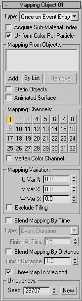
- Type
- Defines the timing used to acquire and apply the mapping. The options are:
- Once on Event Entry Acquires the mapping once, from the closest point on the reference object geometry when the particle enters the event. Use this option if particles are locked to the reference surface.
- Continuous Acquires the mapping continuously during the time a particle is in the current event. If a particle changes location with regard to the reference object, mapping values change according to the closest point at any given time because, in this case, the closest point on the surface is not constant.
This option takes significantly longer to calculate, as the closest point has to be computed for every particle on every frame. Use this option only when necessary.
- Acquire Sub-Material Index
- When on, the Mapping Object operator assigns the material ID from the nearest face to each particle. If the current event or a previous event has a material operator that uses the reference surface material, this option matches particle coloring to the reference surface. This allows you to blend particles to the reference surface for Multi/Sub-Object materials. Tip: Place the Mapping Object operator below a Material operator in the same event. This way, Mapping Object has the final word in assigning the sub-material index to a particle.
- Uniform Color Per Particle
- When on, the whole particle gets the same mapping coordinates. As a result, the whole particle is of the same color since the mapping coords are the same across the particle shape. The mapping coordinates are taken from the surface point on the reference geometry nearest the particle pivot point.
When off, a mapping for a particle is a linear approximation of the mapping at the nearest surface point. It's as though mapping from the reference geometry is projected onto the particle. As a result, vertices of a particle have different mapping coordinates, and a texture on a particle represents a patch of texture from the reference geometry. This method is slower because it requires more complex analysis of the reference geometry.
Mapping From Objects group
These controls let you assign reference objects, from which particles acquire mapping or material IDs.
- [list]
- Lists reference objects.
- Add
- Adds an object to the list.
- By List
- Displays a dialog where you can select multiple objects from a list.
- Remove
- Removes a highlighted object from the list.
- Static Objects
- Indicates that reference geometry is not animated in any way. In this case, the Mapping Object operator acquires mapping and material IDs only once.
- Animated Surface
- When on, the Mapping Object operator updates the surface data at every frame, which is necessary if the reference geometry has surface animation that causes it to change shape. If the object has transform animation only (move, rotate, scale), leave this option off. This option is available only when Static Objects is off.
Mapping Channels group
Choose mapping channels to acquire from the reference surface and assign to particles. You can choose up to 32 channels.
- Vertex Color Channel
- Acquires the Vertex Color channel from reference geometry and assigns it to particles.
Mapping Variation group
- U/V/W Var %
- Enables variation of the mapping values assigned. The variation value is a percentage of the standard 0.0–1.0 mapping space. For example, if the U Var % value is 20.0, then the U mapping assigned to a particle can vary by up to 0.2 from the reference geometry mapping U value.
- Exclude Tiling
- Clamps mapping values to the 0.0–1.0 range. Variations set by U/V/W Var % can cause mapping values to go below 0.0 or above 1.0. With non-tiling textures, this can cause a visual jump in coloring. When this option is on, if the original mapping value is below 1.0, then adding the variation won’t make it larger than 1.0. If the original mapping is above 0.0, adding the variation won’t make it smaller than 0.0.
By default, the acquired mapping values are assigned to a particle as soon as it enters the event. If particles have been assigned mapping values in a previous event, a visual color jump can result. Use Blend Mapping By Time or Blend Mapping By Distance to cause particles to smoothly blend between previous mapping and mapping assigned by the Mapping Object operator in the current event.
- Blend Mapping By Time
- Causes particles to blend smoothly between previous and current mapping by time. Note: When Blend Mapping By Time is on, Blend Mapping By Distance is unavailable.
Type This option defines the timing used for map blending. It is available only when Blend Mapping By Time is on.
The types are:
- Absolute Time Particles finish the blending process by the time they reach the frame specified by the Finish At Time parameter.
- Particle Age Particles finish the blending process by the time they reach the age specified by the Finish At Age parameter.
- Event Duration Particles will finish the blending process after they spend a specific period of time in the current event, as specified by the Finish At Time parameter.
- Limited Change Rate Limits the rate at which a particle can change its mapping. The Turnaround Time parameter defines the time interval required to change the mapping value from its previous value to the current value. The greater the Turnaround Time value, the longer it takes for a particle to change to the current mapping.
- Blend Mapping By Distance
- Causes particles to blend smoothly between previous and current mapping based on the distance from the reference geometry. At every frame, the operator calculates the distance to the closest surface point. As a particle approaches the reference surface, the blending process occurs. The blending is finished when a particle reaches the Finish Distance in relation to the reference surface. Use this option if particles are directed toward the surface upon entry into the event, as with a Find Target operator. Note: When Blend Mapping By Distance is on, Blend Mapping By Time is unavailable.
- Show Map In Viewport
- Displays map coloring in viewports.
Uniqueness Group of Controls
The settings in this group change the randomization of the U Var, V Var, and W Var parameters in the Mapping Variation group.
- Seed
- Specifies a randomization value.
- New
- Generates a new seed using a randomization formula.