Note: The answer is referring to version 2016. This information may differ on other versions.
The workplanes help in the modeling of the structural elements.
There are three methods to create workplanes:
- At the current UCS, in the XOY plane
- By three points
- By origin and Z direction
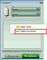
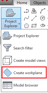
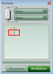
The command for workplane creation is accessible from the Workplanes pane of the Project Explorer and from the Home ribbon tab.
A dialog box appears, allowing you to select the desired creation method.
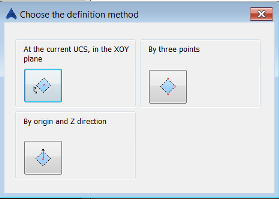
- Defining the workplane at current UCS, in the XOY plane
- The position of the workplane depends on the position and orientation of the UCS, in the XOY plane.
- Select a point where the workplane will be positioned and enter a name for the workplane.
-

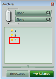
- The workplane is positioned in the XOY plane and the name is displayed next to the lines that define it and in the Project Explorer.
-
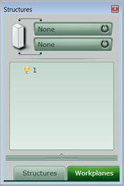
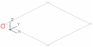
- Define the workplane by three points
- The plane is defined by any three selected points. The new workplane is not dependent on the position and orientation of the UCS. Tip: You can create help-lines in order to precisely define the work plane.
- For example, define three points as in the following picture and name the workplane.
-
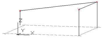

- The new workplane is created.
-
- Define the workplane by origin and Z direction
- Select 3 points, but take into account what each point represents.
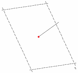
- The first point is the origin of the workplane (the center of the square limited by the dotted lines). This point is the origin of the plane and can coincide with the "First point for direction" (see next step) that defines the Z direction of the workplane.
- The second point is the first point from the segment that defines the Z direction of the new workplane.
- The third point is the second point of the segment that defines the Z direction of the new workplane. With these two points, a line perpendicular to the plane is created.
- The last step is to name the newly created workplane.
-

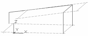
- It can be seen, that the line is perpendicular to the new plane. The position of the workplane does not depend on the position and orientation of the UCS.
-
