You can create a view, using a drawing process from either the Drawing Processes Palette or from the Drawing process manager.
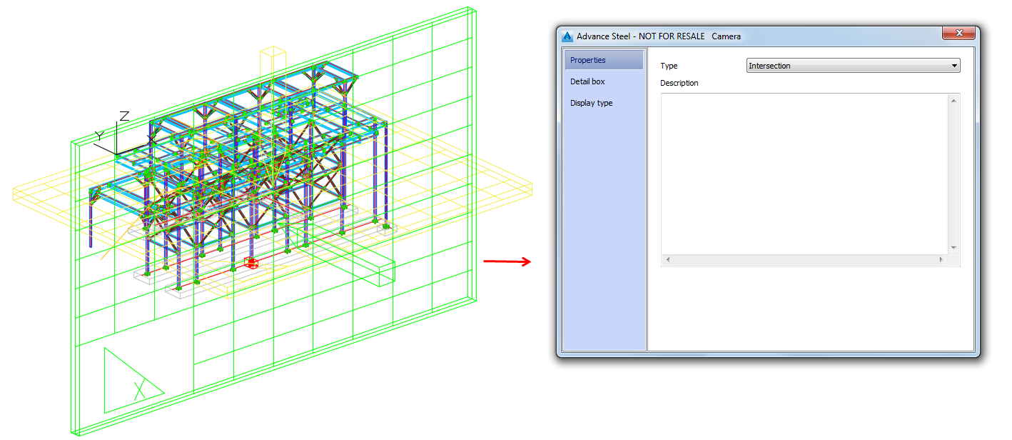
In this example, there are three cameras, each with different properties, set in the Camera dialog, Properties tab, Type field:
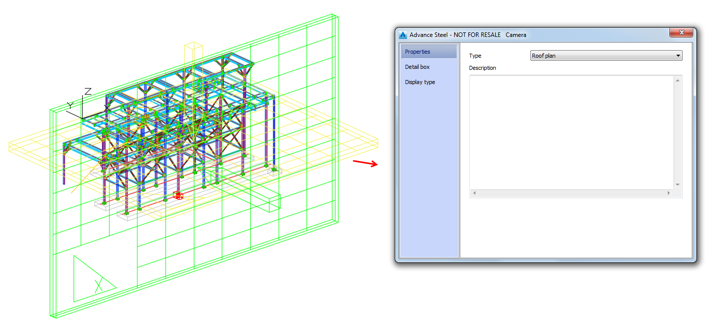
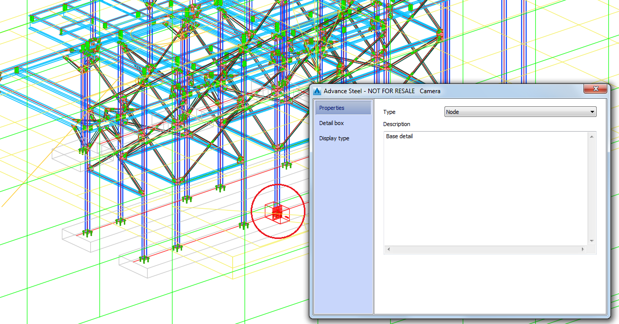
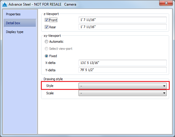
Also, none of them has any drawing style set in the Detail box tab, Drawing style section, Style field:
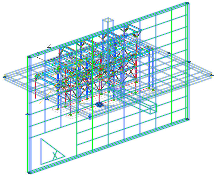
- In the model, select all the cameras.
- Access the
 Drawing process manager, in the
Output tab,
Document Manager panel.
- In the
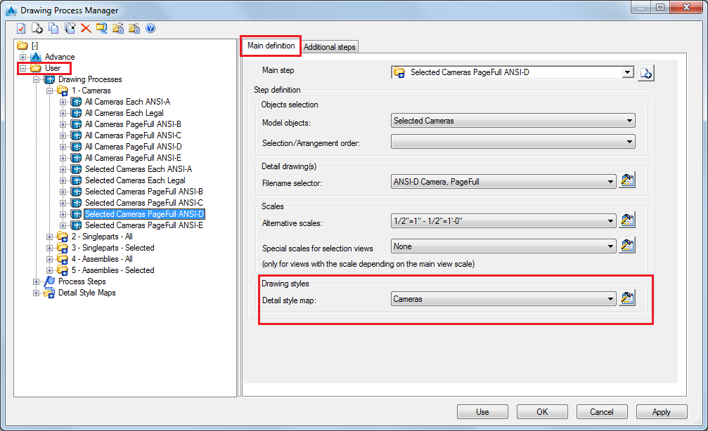
Drawing Process Manager window, go to
User >
Drawing Processes >
Cameras >
Selected Cameras PageFull ANSI-D. In the
Main definition tab >
Drawing styles section, select
Cameras from the drop-down menu.
- Click the
 (Properties) icon on the right of the drop-down menu to see the
Detail style map of the current drawing process.
- Select
Cameras entry in the
Detail style map dialog and move it to the bottom of the list, using the arrows in the top right part of the list:

The drawing styles for cameras used in this process for:
- Camera Intersection is Elevation View - Line.
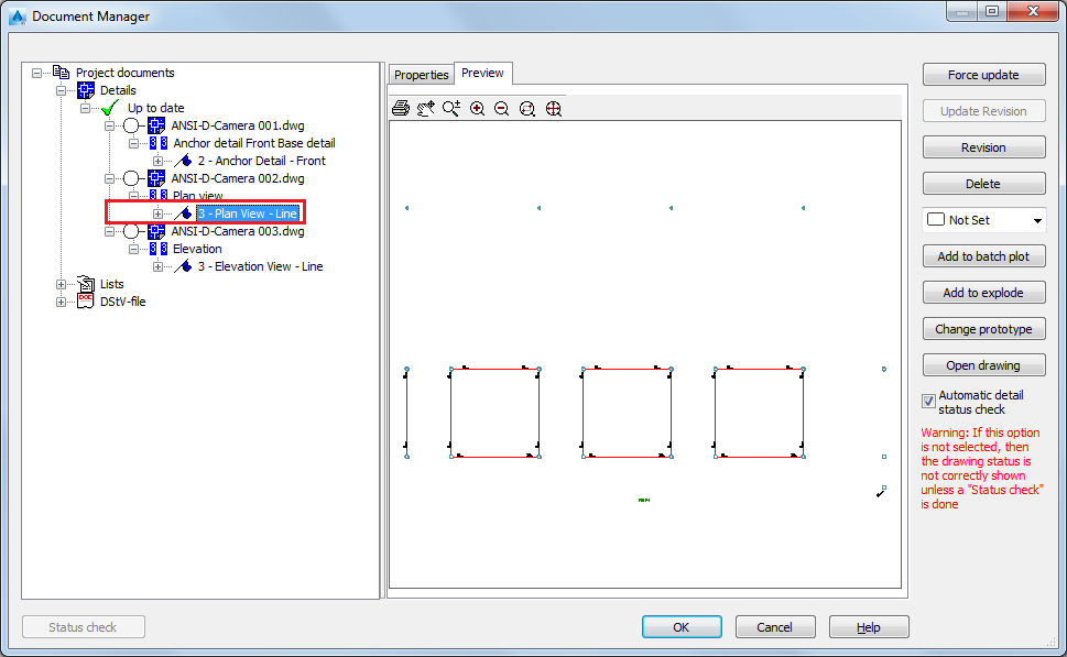
- Camera Roof is Plan view - Line.
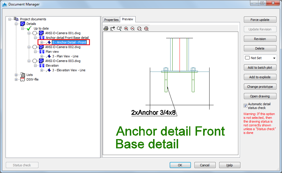
- Camera Node is Anchor Detail - Front.

- Click Apply.
- Click Use in the Drawing Process Manager window.
- Click OK in the Process properties dialog.
- Open the
 (Document Manager), from the
Output tab.
- In the Document Manager window, you can see the created detail drawings.
Your camera details are created using the drawing style set in the process detail map, for each type of camera:

