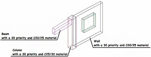
For better management and display of the intersection of concrete elements, Advance Steel provides the option for handling the priorities. These are designed to both interrupt concrete elements with different classes and create continuity between elements. Also, using the priority of concrete elements the concrete casting method is emphasized.
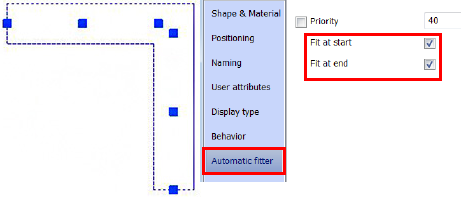
In the properties of the concrete elements the initial priority value is displayed in the "Automatic fitter" tab as follows:
- for linear elements: concrete column, concrete beam, concrete curved beam and continuous footing the priority value is 30.
- for planar elements: concrete rectangular slab and polygonal slab the priority value is 20; wall and polygonal wall the priority value is 40
The priority value can be modified on the "Automatic fitter" tab from the concrete elements property window. For intersections of concrete elements, the edge of the elements with the highest priority value is displayed; the concrete column element is an exception.
The intersection of the two walls with different priority values is displayed in the following figure. Notice that the edges of the intersection displayed are those of the wall with the highest priority value. The wall with lower priority value is cut by the shape of the wall with the highest priority value.

For an intersection between a concrete wall and a beam with different priorities, the intersection edges of the elements with the highest priority value are displayed. Thus, when the beam has a higher priority, the wall is cut by the beam contour and vice versa.

As mentioned above, the rule with the higher priority is not applied for the concrete column element type. This element is considered as a vertical element and it cannot be cut by other elements regardless of the priority value or concrete type.

If the concrete elements have the same priority and the same concrete type, the intersection edges of the elements are not displayed. If the concrete elements have the same priority but different concrete types, the intersection edges of the elements are displayed.


The "Fit at end" and "Fit at start" options are available on the property page of the concrete elements which are created by 2 points (walls, beams and continuous footings). These options allow the junction of the elements at one or both ends. The elements are created with a start and end point; these points are the ends of the elements and correspond to the "Fit at start" and "Fit at end" options.
When the "Fit at start" and/or "Fit at end" options are checked, the elements are automatically extended to the intersection of the common edges, regardless of whether the end elements are entirely or a partially overlapped.

When the "Fit at start" and/or "Fit at end" options are not checked, the concrete elements are not extended; they are displayed with the real lengths.

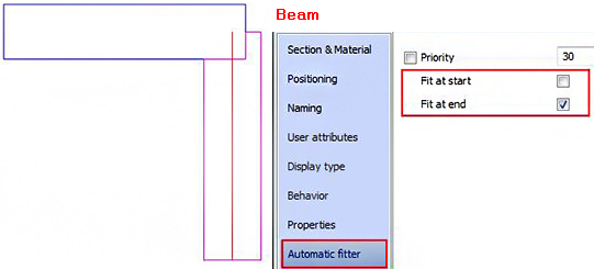
For the intersection between the wall and beam, the beam is the junction related to the wall if the "Fit at start" and/or "Fit at end" options are checked.

For displaying the entire beam (not cut by the wall), one of the "Fit at start" and "Fit at end" options should be unmarked, according to its junction ends.
