NC
Several details regarding how the scribing feature works:
- Scribing works for beams, and recognizes any element attached to them (beams or plates). It does not work for tubes or round elements because they do not have straight surfaces.
- The attached elements must touch the profile on the NC surfaces. Generally, the NC surfaces are the main sides of a beam. For example, the NC surfaces of an I-profile are the sides of the web and the outer side of the flanges, thus only the elements attached to those surfaces generate data for the scribing option.
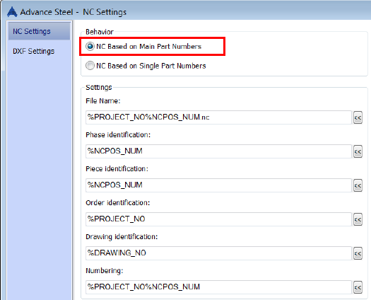
- Scribing is obtained only for the Main Parts. In the NC settings dialog box, the behavior must be defined as NC Based on Main Part Numbers.

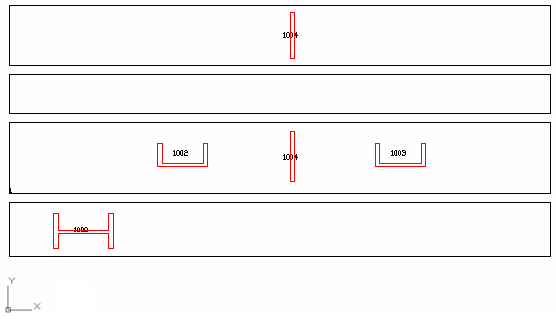
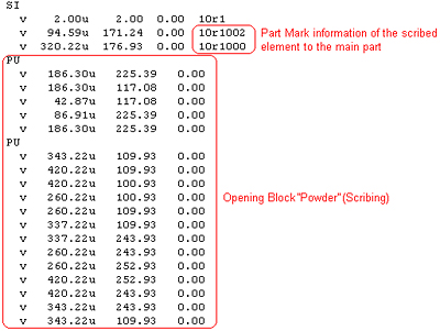
Scribing information will appear in the NC file in the block called PU and as a text in the SI block. Also there will be a contour detailed in the NC-DXF file.
DXF
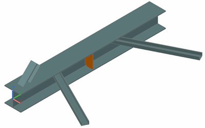
In the following example a main beam with attached parts is used.
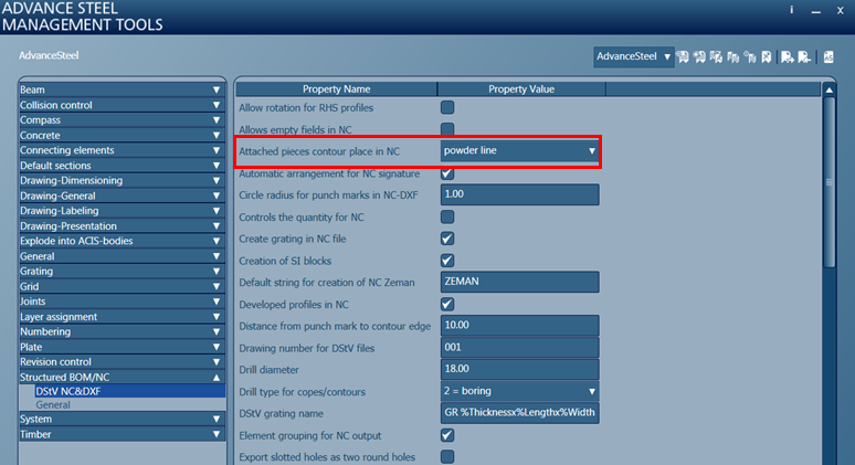
Scribing information will appear in the NC file in the block called PU (powder) or KO (punch) according to the "Attached pieces contour place in NC" default. The difference between block names will be recognized by the NC machine, as the information inside the block is identical in both cases.
When the default is set to 0 the main part and attached part contour is described in the PU block and when the default is set to 1 the pieces contour is described in the KO block. In DXF there will be no difference between the two settings, and the contour will appear with a red line describing the scribing on the attached part on the main part.
In addition, there is also a default available to display information (based on tokens) about the attached part only in the NC file. The default is called "Text for attached object contours in NC".
The tokens that can be used for this default can be one of following:
- %PROJECT - to display the project name
- %PROJECT_NO - to display the project number
- %CLIENT - to display the client name
- %BUILDING - to display the building name
- %BUILDING_LOCATION - to display the building location
- %CONTRACTOR - to display the contractor name
- %DATE_ORDER - to display the data order
- %DESIGNER - to display the designer name
- %DATE_CONSTR - to display the data
- %DETAILER - to display the detailer name
- %MODEL_DWG - to display the model .dwg name
- %DRAWING_DWGs - to display the drawing name which the elements are detailed
- %DRAWING_NO - to display the drawing number
- %SinglePartPosNum - to display the single part mark
- %SPDRAWING_NO - to display the single part drawing number
- %NCPOS_NUM - to display the NC part mark
- %POS_NUM - to display the part mark
- %UserAttr1 - to display the value from User Attribute 1
- %UserAttr2 - to display the value from User Attribute 2
- %UserAttr3 - to display the value from User Attribute 3
- %UserAttr4 - to display the value from User Attribute 4
- %UserAttr5 - to display the value from User Attribute 5
- %UserAttr6 - to display the value from User Attribute 6
- %UserAttr7 - to display the value from User Attribute 7
- %UserAttr8 - to display the value from User Attribute 8
- %UserAttr9 - to display the value from User Attribute 9
- %UserAttr10 - to display the value from User Attribute 10
- %UserProjAttr1 - to display the user project attribute 1
- %UserProjAttr2 - to display the user project attribute 2
- %UserProjAttr3 - to display the user project attribute 3
- %UserProjAttr4 - to display the user project attribute 4
- %UserProjAttr5 - to display the user project attribute 5
- %Material - to display the display the material

Below is the result in the NC & DXF files:

