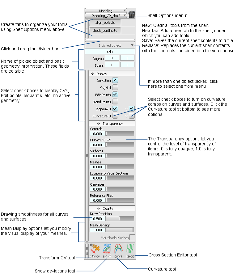
Modeling control panel
Trash

The Trash icon lets you remove tool icons or shelves from the shelf area. To get rid of an unwanted item, drag it into the trash while holding down the middle mouse button.
The shelf area
The shelf area contains shelves, which are sets of tools you can customize to help with your workflow. You can change the contents and number of shelf sets in this area, and compress them or expand them by clicking the tabs.
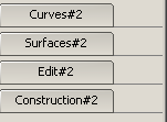
This area also lets you have more window real estate by offering a compact alternative to the main shelf window. For example, you can put all the symmetry tools in the shelf set area and then close the main shelf and palette windows for a larger view of your model.
Shelf Options
Click the Shelf Options tab for a drop-down menu that lets you add, save, clear, and replace shelf sets in the shelf area.

New
Deletes all default shelf sets and creates a shelf.
New Tab
Creates a shelf tab.
Save
Saves the customized shelf set.
Replace
Replaces one customized shelf set with a second customized shelf set.
This enables you to create and change shelf files.
Pick list
The Pick list isolates a single curve or surface from a collection of curves and surfaces. The white text field displays the name of the picked component.

You can pick more than one object in Alias. The gray text box tallies all picked (and active) components in the modeling space. To view a drop-down list of all selections, and to switch between components, click and hold on the gray text box.
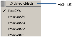
As you move the mouse pointer over an item, the object is highlighted in the view windows. Release the mouse button over an object to pick only that one.
To rename a picked object, type the new name into the white text field.
Rebuild
The rebuild tool can work with several curves or surfaces at a time. The Control Panel indicates "# picked curves" or "# picked surfaces". If the objects have a different degree or number of spans in U or V, the corresponding field is blank.
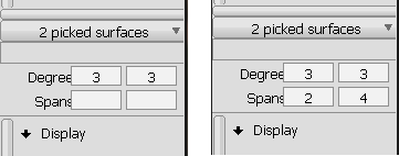
Two surfaces with different numbers of spans are given 2 spans in U and 4 in V.
If you select both curves and surfaces, the Control Panel indicates "# picked objects" but does not let you enter values for Degree or Spans.
The Rebuild options let you quickly change the degree (from 1 to 9) and the number of spans of the picked curves or surfaces through one of the following methods:
- Click the number field and enter a new value.
- Click the arrowhead that appears when you roll over the number field, and choose a value from the drop-down menu. The first two choices at the top of the menu are + and -, which increase and decrease the current value by 1 respectively.
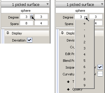
If the degree or spans of a curve or a surface are modified, this tool maintains the original distribution of spans while creating additional ones as needed, and does not change the parameterization of the geometry.
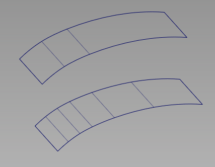
Surface with 3 spans in the U direction (top) is rebuilt with 6 spans in U (bottom).
For a surface, changing the degree or number of spans in one direction (U or V) does not affect edges running in the other direction.
When a degree or span value is modified:
- The geometry updates to show the changes.
- The prompt line displays the largest deviation value between the old and new geometry, on which object it is found, as well as the new(old) degree and number of spans.
- Two buttons appear in the active window. Click Accept to keep the changes. Click Cancel to undo the changes and revert to the previous value. Choosing a different tool without clicking any of the buttons also cancels the changes.
Display
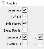
For a better view of your design, the Display options let you display or hide the following items on the picked geometry:
- Deviation locators
- Cv/Hull
- Edit points
- Blend Points
- Isoparametric curves
- Curvature locators
Transparency
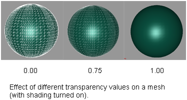
This set of options lets you control the level of transparency of geometry and other items such as locators and canvases.
Transparency is achieved by blending the object color into the background color.
These sliders are also available from WindowDisplay > Transparency
 .
.
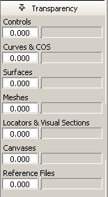
A value of 0.0 means the item is completely opaque. A value of 1.0 means the item is completely transparent and invisible.
Quality
This set of options lets you adjust the display of your curves, surfaces, and meshes.
However, it only affects the visual display of the geometry, not the geometry itself.
Draw Precision
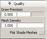
Use this slider to control the drawing smoothness of all curves and surfaces. The slider value goes from 0.0 (rough approximation) to 1.0 (very smooth). The default is 0.5.
This value applies to all existing curves and surfaces, as well as all new curves and surfaces created from this point on.
Mesh Density
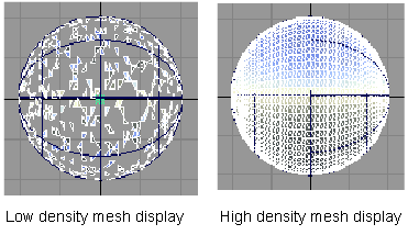
Use this slider to control which percentage of the triangles are displayed. By default, the slider is set to 1.0 (all the triangles are drawn). Drawing less triangles increases performance speed.
Flat Shade Meshes
When this option is turned on (check mark visible), flat shading is applied to the mesh when using one of the diagnostic shading modes. Each triangle is rendered in a single color, producing a faceted effect.
Tools
Clicking on one of the tools in the bottom row of the Modeling Control Panel opens up an option sub-panel for that tool. These options are described on the following pages.