Animation > IK > Add IK Handle
Applies IK handles constraints to affect IK skeletons.
Add IK Handle Options
Solver
These are the types of IK solvers you can use. Pick one of the following:
Multi-handle – Click to use the Multi-handle solver. This option creates an IK handle that controls a skeleton chain, but allows overlapping with other IK chains.
Single-chain – Click to use the default Single-Chain solver. This option creates an IK handle that controls a non-overlapping IK skeleton chain.
Spline-handle – Click to use the Spline-handle solver. This option creates a Spline handle that controls a skeleton chain along a spline curve.
Orientation
Local – This option lets you control the handle’s orientation relative to the root joint.
World – This option lets you control the handle’s orientation in world space. This means that the rotation plane is controlled by an IK handle that can be fixed in world space instead of relative to the root joint. You can also set this attribute from the Information Window after the IK handle is created.
Set rest pose
When this option is ON, the current pose becomes the rest pose for the joints in the chain controlled by the IK handle.
This option is the same as choosing Edit > Rest Pose > Set Rest Pose and then Objects > Add IK handle.
Multiple handle options
Weight Type
Weights are useful if you have constrained an object to more than one other object. This way you can weight the different constraints, so that a constrained object tends to meet one constraint more than another.
Weight
You can change the weight value either by using a preset weight (Sticky, Low, Medium, High); by clicking in the field, typing a value and pressing  ; or by dragging the slider bar. Weights can be animated.
In general, if you know that you won’t have conflicting constraints, or if you want all constraints to be weighted equally, it is best to use the Sticky weight (2.00) or some other low value for the weight. Higher weight values make the IK stiff, and harder to solve.
Goal Type
Position – Selects the rotate pivot position of the joint.
Orientation – Selects the same orientation as the object.
Both – Selects both the position and orientation.
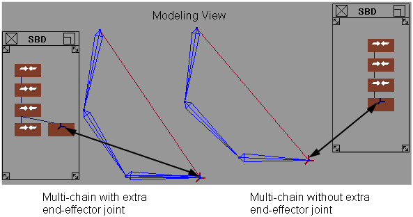
Create end-effector
As shown in the following diagram, this option creates an extra joint node beside the IK handle.

Single chain options
Control Type
Translation – This is the default control setting, suitable for most basic IK use. Translation means that you can move or animate the IK handle’s translation channels.
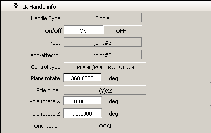
Plane Rotation – This setting gives you more in-depth control of the IK handle. It lets you rotate the skeleton plane, the plane in which the joints contained in the IK handle lie. If all the joints of the IK handle do not lie in one plane, a “best” fit plane is chosen.
The rotation of the plane axis can also be controlled by picking the IK handle and using the  with the Rotate tool (Transform > Rotate
  ).
).
Plane and Pole – In some cases, the combination of translation and plane rotation might cause the IK solution to flip uncontrollably. This setting provides advanced, specialized control of the IK handle to avoid this situation. Set the Pole rotate X and Pole rotate Y values (found in the IK Handle info section of the Information Window) to alter the plane of the skeleton while keeping the pole in the same orientation relative to the skeleton plane.

Spline handle options
Position Type
Spline handles can define positions on a curve either by parameters or by arc-lengths. Both types of measurement use relative percentage values.
Twist Type
The Twist Type menu allows you to choose how to distribute the twist angle defined on a handle to its joints.
Linear – The joints twist equally at each joint.
Fast Out Slow In – Joints near the root twist more than joints near the end.
Slow Out Fast In – The joints near the root twist less than the joints near the end.
Ease Out Ease In – Joints in the middle twist more than joints at the ends.
Twist Root
Set this option ON to define the twist starting from the root joint. If set to OFF, the twist starts from the second joint.
Create Root handle
Set this option ON to create a root spline handle at the root of the chain controlled by the master spline handle. If set to OFF, only a master spline handle is created.
Create Curve
You do not have to pick an existing curve if you select this option. Instead, a new curve is automatically created. This new curve will match the chain defined by the new handle. The curve will be grouped as a sibling of the root joint.
Snap Curve to Root
If you do not want to create a new curve, pick an existing curve. If you select Snap Curve to Root, the picked curve is snapped so that the first CV matches the root joint of the new handle. Otherwise, the curve does not move. Instead, the root and the chain move to the curve.
Limitations for IK handles
-
Scaling a skeletal chain with an IK handle may cause the skeleton to respond incorrectly.
Turn off the IK handles, scale the skeleton, and turn the IK handles back on. If you scale the chain non-proportionally, delete the IK handle and then reapply it.
-
The spline handle solver may generate a solution in the range (-180 degree, +180 degree) for each of its joints.
This may result in problems when rendering with motion blur or rendering on fields, as the interpolation will not be correct if the solution jumps from one end of the range to the other between two frames.
Use Run IK with the Motion Blur or Field compensation options or both. Disable the handles after RunIK or the desired animation will not be written out to SDL.
Note:A spline handle is always constrained, so if it is turned on it will solve and override any animation on the skeleton.
-
Cumulative rotations of more than 360 degrees with spline handles may cause geometry to flip.
-
Use the Anti Flip Controls on the Root Handle in the Information window to find a setting which keeps the rotations coherent.