Utilities > SBD > SBD Window
Shows or hides the SBD window, which lets you view the internal structure of objects and groups in the scene.
Use the Object Lister to see a structured view of the objects and components in the scene. See Windows > Object Lister.
The SBD window is like a view window, except instead of showing a visual representation of your scene, it shows a graph of the internal structure of the scene in the computer.
Alias keeps track of every aspect of the scene in a data structure equivalent to a graph. Curves, surfaces, groupings, transformations, components, lights, and everything else in the scene is represented by nodes in the graph. This graph is called the Scene Block Diagram.
Nodes in the graph (sometimes called DAG nodes) represent the “main” objects in the scene: curves, surfaces, curves on surface, lights, locators, and so on. Many things you can manipulate in the view windows, such as CVs, do not have their own DAG nodes. They are stored as part of an object’s internal information.
The SBD window
| To... | Do This |
|---|---|
| Navigate around the SBD window. | Use the same camera move techniques as in orthographic view windows: middle mouse button tracks, right mouse button dollys in and out. |
| See the names of objects. | Dolly in close enough that the labels will fit on the nodes. |
| Pick objects and components from the SBD window. | Use the same pick tools as in the modeling windows. |
Types of nodes
-
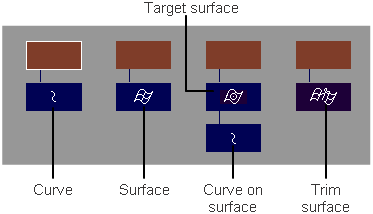
Positioning node – The brown positioning nodes contain the transformations applied to the geometry nodes below it in the graph.
-
Geometry node – The blue geometry nodes contain the internal structure of a piece of geometry (edit points, CVs, and so on).
Different types of geometry are indicated by different icons in the blocks.

Top-level objects vs components
Top-level objects are top-level nodes in the SBD hierarchy. Components are nodes grouped beneath top-level objects. The Pick > Object  tool picks top-level objects. The Pick > Component
  tool picks objects from anywhere within the hierarchy.
The SBD window shows the difference between the Pick > Object  and Pick > Component
  tools. For example, consider this SBD representation of a cube object:
You can see that the cube is constructed from six planes which are grouped together.
-
If you choose Pick > Object
 and pick the cube in a view window, the windows will show that the grouping node is picked.
 -
If you choose Pick > Component
 and turn on the Surfaces filter button, then pick the cube in a view window, both the windows will show that only one “face” plane of the cube is picked.
Instead of picking the entire group, the Pick > Component
 tool picked one of the sub-nodes.