Surface Edit > Trim > Trim Surface
![]()
Trims or splits surfaces using curves-on-surface or cross sections.
Trim Control
3D Trimming
If this box is checked, you can trim the surface along projected curves and cross sections, or you can select a surface and generate a trimming curve automatically from the intersection with the target surface. By default it is unchecked.
Method
Displays when 3D Trimming is selected.
Project – Creates trimming curves by projecting the selected curves onto the target surface.
Intersect – Creates a trimming curve from the intersection of the selected surface and the target surface.
You can use the Project or Intersect method in a single trimming operation by toggling back and forth between them.
Create History
If this box is checked, the projected curves have construction history. Editing or transforming the curves and surfaces causes the projection and trim operations to be re-executed.
This option is only available if 3D Trimming is turned on.
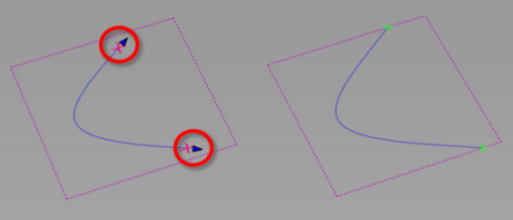
Extend
Extend a curve that does not project entirely on the patch, either automatically or manually, and continue the trim operation without leaving the tool.
Auto
When the trim fails, any curves-on-surface that are within the set Tolerance of another curve-on-surface or boundary are extended and the trim is attempted again.
Selected
A trim extend arrow appears on the curve that needs extending. Clicking the arrow snaps the end of the curve to the patch edge.
Vector Options
These options are only available if 3D Trimming is turned on.
X, Y, Z
Specifies a projection vector along that axis.
View
Specifies a vector normal to the current view. The vector is not drawn in the view windows.
If the current view is changed, click Refresh View Vector to update the vector.
You can project different curves along different views vectors. However, if you click Refresh View Vector, or select a different vector option, all curves-on-surface are updated to match the current projection vector.
Picked
Lets you specify the name of an existing vector in the Picked Vector field, or pick the vector in the view.
Normal
The curve is projected onto each point on the surface along the normal at that point, instead of along a single vector direction.
Picked Vector
This text field only appears when Picked is selected. It displays the name of the selected vector object. Alternatively, you can type in the name of a vector object.
Refresh Vector
This button only appears if View is selected. Click it to update the vector if the view has been modified
Retain Vector
Click this button to create a vector construction object in the view windows.Otherwise, the tool uses the vector direction you specified, but you are not able to see and re-use the vector.
Create Vector
Click this button to create a projection vector.
Click in the view to place the start point of the vector, or type the position and press  . Use the vector manipulator to position the vector then click Accept.
Limit Projection
![]()
Use this option to limit the projection distance of curves along the specified projection vector (Vector Options) so that the curves do not automatically get projected through the target object. When trimming closed objects, this allows you to control the distance from the surface or depth of the trim, rather than trimming through both walls of the target object.
Adjust the Positive Distance and the Negative Distance values to specify the projection distance from the current position of the projected curve. Use the in-canvas arrow manipulator or enter values for Positive Distance and Negative Distance in the set measurement units.
Display Options
Show Intersections
If this box is checked, green locators indicate the intersections between the trim curves, and between the trim curves and trim surfaces. Yellow locators indicate trim curve endpoints that do not intersect any other curve-on-surface or trim surface edge.
Show Preview
If this box is checked, a preview of the trimmed surface is highlighted yellow.
Region Selector Length
Adjust the value if the selectors (crosses) appear too small or too large on your model. Displays trim locators based on pixel size rather than based on the size of the surfaces to be trimmed.
The Shrink Surface option has been replaced by a plug-in called shrinkToTrim which can be loaded through Utilities > Plug-in Manager  . shrinkToTrim shrinks the UV parameters of the underlying surface to cover only the visible (non-trimmed) parts of the surface. This functionality is useful when applying label-style textures to the surface.
Control Options
Chain Select
If this box is checked, selecting a curve to project also selects all other curves that are tangent continuous with it.
Subdiv Select
![]()
Turn this on when trimming the surface of subdivision objects. When on, the Trim tool behaves the same way with subdivision objects as it does with NURBS surfaces. Subdiv Select is on by default.
Trim Divide History
If this box is checked, trim divided surfaces are linked together with history so that subsequent modifications to one of the divided surfaces are reflected in the other.
Mouse Defines Action
If this box is checked, the mouse buttons control the trim mode. The left, middle, and right mouse buttons are mapped to Keep, Discard, and Divide, respectively. Click the trim region with the appropriate mouse button and press the spacebar to complete the trim.
Show Last Selectors
If this box is checked, the last trim region selectors are saved and restored after untrimming. If after untrimming you want to make changes and retrim, you only have to add or move the selection locators for the changes you are making. You do not have to reclick all the original ones.
Continuity Check
![]()
Adds a surface continuity locator to the trimmed surfaces, providing a pass or fail indication on continuity and showing any discontinuities. This option is available when the 3D Trimming method is set to Project.
Continuity Check Type
When Continuity Check is on, you can choose to check for a specific level of continuity. Choose an option from the Continuity Check Type list, which includes G0 Position, G1 Tangent, or G2 Curvature.