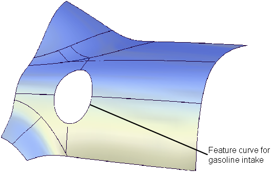
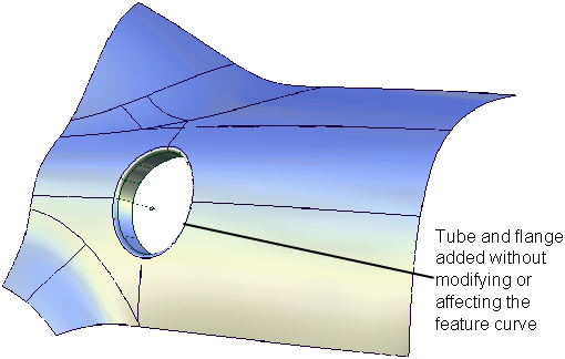
Surfaces > Rolled Edge > Tube Flange
Creates a finish on the edges of a surface model.
By using one or more of the following: edge, curve-on-surface, boundary edge, or iso-parametric line, the tool creates a tube that touches the selected geometry. The tool also creates a linear extension — a flange — on the tube. This extension can be defined by a sweep angle or a vector plus a draft angle.
Tube Flange Control options
Tube
Continuity
Choose either G1 Tangent or G2 Curvature continuous to the base surfaces.
Radius
Defines the radius of the tube, when Continuity is set to G1 Tangent.
If Variable is set to Radius, you can create a variable radius interactively by adding more radius manipulators along the curve. However in that case, the Radius option is grayed out and you must define the radii interactively on the model by dragging the manipulators.
Flip
Enables you to put the tube and flange on top of, or underneath the surfaces. You can also click the blue arrow manipulator on the model to flip the side.
Specify
Choose whether you want to specify the Center radius, the Tangent offset, or Both.
If Specify is set to Center radius or Tangent offset, and you also set the Form factor, the third parameter (either Tangent offset or Center radius) varies along the fillet. Both lets you specify both the Tangent offset and Center radius of the fillet, but not the Form factor. The form factor is calculated automatically from these two values and varies along the fillet.
Center radius
Radius at the center of the tube (as measured along the arc length).
Tangent offset
Radius of a sphere that is tangent to the input surface(s) at the contact line, and is also tangent to the flange surface. (The contact line is the line along which the new tube surface touches the input surfaces.)
Visually, it corresponds to the radius of the blue arc manipulator visible on the model (when Variable is set to Radius).
Form factor
This parameter lets you adjust the shape of the tube while keeping either the Center radius or Tangent offset constant. It specifies the ratio between the lengths of the innermost and outermost CV arms of the hull in the V direction of the tube. Possible values range from 0.1 to 2.0.
In the example below, we specify the tangent offset to be 60.0. Changing the form factor causes the center radius to vary.
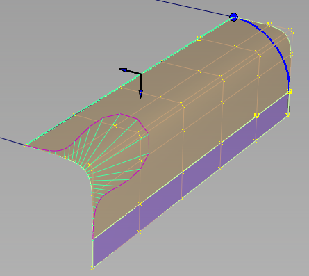
Form factor set to 0.1, creating a small center radius and a sharper bend in the tube.
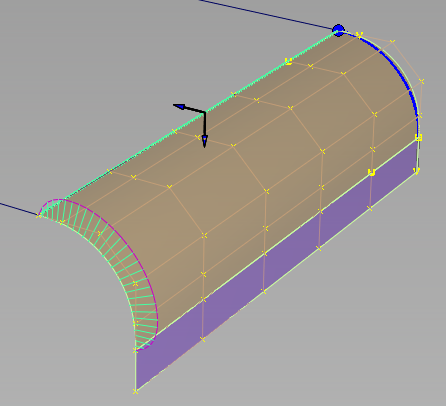
Form factor set to 2.0, creating a large center radius and a more circular tube shape.
The Specify, Tangent offset and Center radius options are only available if a single radius manipulator is used. If the tube has more than one manipulator (which in fact control the tangent offset), then the Form factor directly controls the center radius.
Flange
Type
Set to either Sweep angle or Parting line. Sweep angle defines where along the tube the flange will be tangent to the tube. Parting line uses a vector and draft angle that determines the direction of the flange. If you select Parting line, you must pick a vector, or specify it through the Parting Line Vector Options.
Sweep Angle or Draft Angle
Provides a slider to control the angle. The default is 90 degrees for Sweep, and 0 for Draft angle. Either angle can be variable.
Flip
Enables you to flip the direction of the flange. This option is grayed out if at least one of the input curves is an edge, and thus, there’s only one valid orientation of the flange.
Create Flange
Determines whether or not a flange will be built off the edge of the tube. To create a full tube, use a Sweep Angle of 360 degrees. Note that the tube will be trimmed according to the Sweep Angle or Parting Line settings, even if Create Flange is off.
Length
Determines the length of the flange that will be built, if Create Flange is on. Length can be variable.
Explicit Control
Gives you controls of the surface degree and maximum number of spans in the tube and flange surfaces.
Explicit Control Options
This section is only available when Explicit Control is checked.
(Length) U Degree
The degree of the tube and flange surfaces in the U direction (that is, along their length). Enter a whole number from 2 to 9.
(Section) V Degree
The degree of the tube surface in the V direction (that is, along its section). Enter a whole number from 3 to 6 (or 5 to 6 if Continuity is set to G2 Curvature).
Max. Spans
The maximum number of spans in the entire tube and flange surfaces if Surface Type is set to Single surface, or per surface if Surface Type is set to Multiple surfaces. This option is only available when Bezier Surfaces is unchecked.
Parting Line Vector Options
These options only apply when Flange Type is set to Parting line.
X,Y, Z
Select one of these to specify a pull direction along that axis.
View
Select this option to specify a pull direction normal to the current view. The vector is not drawn in the view windows.
If the current view is changed, click Refresh View Vector to update the vector.
Picked
Selecting this option lets you specify the name of an existing vector in the Picked Vector field, or pick the vector in the view. This vector defines the pull direction.
Refresh View Vector
This button only appears if View is selected. Click it to update the vector if the view has been modified.
Retain Vector
Click this button to create a vector construction object in the view windows. Unless you do this, the vector direction you specified is used by the tool, but you will not see and be able to re-use the vector.
Create Vector
Click this button to create a parting line pull direction vector.
Click in the view to place the start of the axis, or type the position and press  . Use the vector manipulator to position the vector and click Accept.
Tube Flange Range
Modify Range
When this option is selected, Start and End sliders appear in the control window, and arrow manipulators appear on the selected flanges. Drag these arrows to modify the extent of the flanges across the input surfaces.
Start/End
Use these sliders to modify the extent of the tangent line that is used to build the fillet. Start and End values of 0.0 and 1.0 respectively, define the original extent.
Surface Structure
Surface Type
If you choose Single surface, a single tube surface is built. If you choose Multiple surfaces, the tube is split at curve boundaries, which also include surface boundaries, since a curve cannot span more than one surface.
Bézier Surfaces
This option only appears if Surface Type is set to Multiple surfaces. If it is checked on, each surface will be a Bézier patch.
Bézier patches have a single span, and their maximum degree in the U direction is set through the Explicit Control section. The default is degree 5.
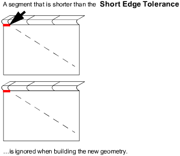
Short Edge Tolerance
In the case of cross-knot insertion, the system will not allow spans of a linear distance less than the Short Edge Tolerance.
Control Options
Note that only one of the three parameters can be variable. For example, it is not possible to create a variable radius tube with a variable length flange.
Variable
Gives you the ability to interactively modify the Flange Length, Flange Angle, or Radius.
Auto Update
Choose between updating changes by selecting the Update button, or automatically updating changes.
If Auto Update is set off, use the spacebar to press the Update button.
Inter Continuity Check
Checking on this option displays continuity locators between the output surfaces, indicating whether or not they are tangent continuous. Green T locators indicate that the surfaces are tangent continuous while red/yellow T locators indicate they are not.
The Continuity Angle fromPreferences > Construction Options is used when testing for tangent continuity, and a shared boundary is only checked if it doesn't present any gap larger than the Topology Distance tolerance (also found in Construction Options).
Only natural (non-trimmed) edges are checked.
Continuity Check
Choose whether to get visual feedback about continuity (set in the Tube section). Green indicates success; yellow indicates that the continuity condition has not been met.
Chain Select
If this box is checked, selecting a surface curve also selects all other surface curves that are tangent continuous with it.
Create Metadata
Specifies whether or not the Tube Flange tool creates history metadata.Note: The Create Metadata option is available only with Autodesk Alias 2019.2 or later.
Variable controls for this tool are provided in the modeling window.
Controlling the Variable parameter in Tube Flange
The variable parameter (Radius, Flange angle, or Flange length — as specified by Variable in the control window) is controlled using a set of manipulators in the modeling window. Only one of the parameters can be varied: the other two are held constant.
Despite its name, Radius controls the Tangent offset, not the Center radius.
Each manipulator consists of two handles — the rail slider and the value handle — only one of which can be active at a given time. The active handle is shown in light blue. The rail slider, a "ball" sliding along the rail, indicates the position on the rail where the value applies. The value handle, an approximate cross section of the future surface, controls the value of the parameter at this point.
The value of the active handle is shown on the prompt line.
For all of the following operations, use the  , unless stated otherwise.
To activate a handle, click it.
To de-activate the currently active handle and switch back to the picking mode, click anywhere on the screen (without dragging the mouse).
To add a new manipulator,  -click the desired point on the rail.
To move a manipulator, drag the slider using the . Alternatively, activate the slider and type in the position (in the range from 0 to 1) along the rail.
To adjust the parameter value, click and drag the value handle. Once the handle is active, the mouse can be dragged anywhere on the screen. Alternatively, activate the handle and type in the value in current units.
To delete a manipulator, -right click it.
If a single manipulator is used, the parameter is constant, and its value can also be adjusted in the control box. As soon as another manipulator is added, the value in the control box is grayed out.