Surfaces > Rolled Edge > Tubular Offset
Creates a tube and intersects the tube with input surfaces to generate offset curves. Also creates tube surfaces.
Use this tool to create a tube that may traverse many tangent-continuous surfaces, and optionally intersect the tube with the input surfaces to generate offset curves. For input, use a curve or series of tangent continuous curves: it may be curves-on-surface, isoparametric curves, or boundary edges. Free curves can be used for creating tube surfaces.
Tubular Offset Control options
Surface
With the Tube option, the resulting geometry is a full tube. Using the Groove option results in the part of the tube on either side of the surfaces which the tube intersects. Choose None to create no geometry.
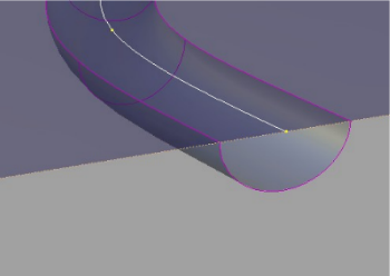
This image shows a surface created by using the Tubular Offset tool with Groove option. Notice the top surface can be trimmed to reveal the groove. This option is useful for representing parting or cut lines.
Radius
Defines the radius of the tube. Create a variable radius interactively by adding more radius manipulators along the curve. Adjust the radius of the tube interactively by dragging its manipulator.
Flip
The Flip option (only available if you have chosen the Groove option) enables you to flip the groove onto the other side of the input surfaces to create a bump. On-screen manipulators indicate which side the tube will be built on.
Tangent Offset, Normal Offset
The tube can be offset from the original input data along the tangent from the input data, or normal to the surface from the input data. On-screen manipulators update interactively to show the position of the tube.
Surface Structure
Surface Type
If you choose Single surface, a single tube surface is built. If you choose Multiple surfaces, the tube is split at curve boundaries, which also include surface boundaries, since a curve cannot span more than one surface.
If curves-on-surface are created at the edges of the tube surfaces (see Trim Type option below) they are segmented to correspond to the multiple tube surfaces.
Bézier Surfaces
This option only appears if Surface Type is set to Multiple surfaces. If it is checked on, each surface will be a Bézier patch.
Bézier patches have a single span, and their maximum degree in the U direction is set through the Explicit Control section. The default is degree 5.
Control Options
Trim Type
The options in Trim Type enable you to select between the creation of curves-on-surface where the tube surface intersects the base surfaces, or to automatically trim away the area of the input surfaces that is contained within the tube. If the Trim Type is set to Off, the input surfaces are left untouched.
Auto Update
Choose between updating changes by selecting the Update button, or automatically updating changes.
If Auto Update is set off, use the spacebar to press the Update button
Inter Continuity Check
Checking on this option displays continuity locators between the output surfaces, indicating whether or not they are tangent continuous. Green T locators indicate that the surfaces are tangent continuous while red/yellow T locators indicate they are not.
The Continuity Angle fromPreferences > Construction Options is used when testing for tangent continuity, and a shared boundary is only checked if it doesn't present any gap larger than the Topology Distance tolerance (also found in Construction Options).
Only natural (non-trimmed) edges are checked.
Chain Select
If this box is checked, selecting a surface curve also selects all other surface curves that are tangent continuous with it.
Create Metadata
Specifies whether or not the Tubular Offset tool creates history metadata.
The Create Metadata option is available only with Autodesk Alias 2019.2 or later.
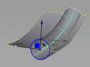
Controlling manipulators in Tubular Offset
Each manipulator consists of two handles — the rail slider and the radius handle — only one of which can be active at a given time.
The active handle is shown in light blue. The rail slider, a "ball" sliding along the rail, indicates the position on the rail where the radius applies. The radius handle, an approximate cross section of the future surface, controls the radius at this point.
The value of the active handle is shown on the status line.
For all of the following operations, use the  , unless stated otherwise.
- To activate a handle, click it.
- To de-activate the currently active handle and switch back to the picking mode, click anywhere on the screen (without dragging the mouse).
- To add a new manipulator,
 -click the desired point on the rail.
 - To move a manipulator, drag the slider using the . Alternatively, activate the slider and type in the position (in the range from 0 to 1) along the rail.
- To adjust the radius value, click and drag the radius handle. Once the handle is active, the mouse can be dragged anywhere on the screen. Alternatively, activate the handle and type in the radius in current units.
- To delete a manipulator, -right click it.
- If a single manipulator is used, the radius is constant, and its value can also be adjusted in the control box. As soon as another manipulator is added, the value in the control box is grayed out.