Alias Theory Builder
Surface Evaluation – Reflection Lines & Iso-Angles
What we are attempting to achieve with surface evaluation is a prediction of what the design will look and feel like when it is manufactured. There is no single evaluation technique that can do this for us, and so we use a range of techniques to build up a picture of the surface quality, and to give us confidence that the data we hand over will create the quality of product that we are expecting.
All of the tools, in one way or another, measure the changing surface normals across the surfaces. The difficulty is how to display this analysis in a way that is meaningful to the designer.
The first method is to display evaluation 'stripes' (or 'reflection lines'), and there are a number of tools for this in Diagnostic Shade. They are often thought of in the same way, but there are important differences in the way the stripes are calculated:
Reflection Lines
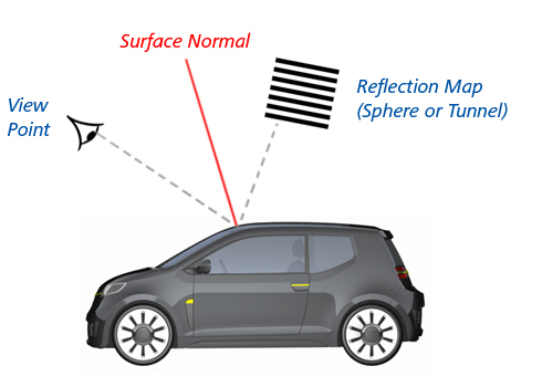
- Calculates the angle of the surface normals with respect to the viewpoint.
- Tumbling the view moves the reflection lines across the surface.
- Quick and easy to use.
Iso-Angle
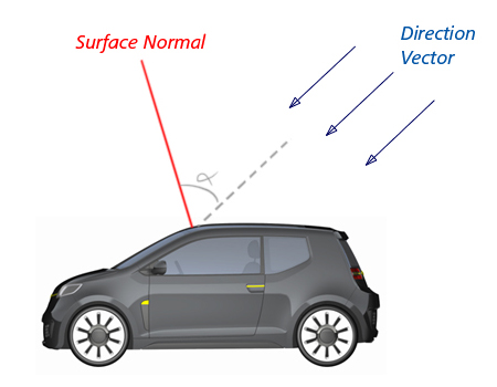
- Calculates the angle of the surface normals with respect to a vector.
- Tumbling the view has no effect on the lines displayed on the surface.
- More accurate and reproducible.
Reflection Lines
The surface reflects a set of constant width lines, and this reflection can be analyzed for breaks in the lines, or uneven variations that may indicate problems with the surface.
There are two reflection line tools which work in slightly different ways:
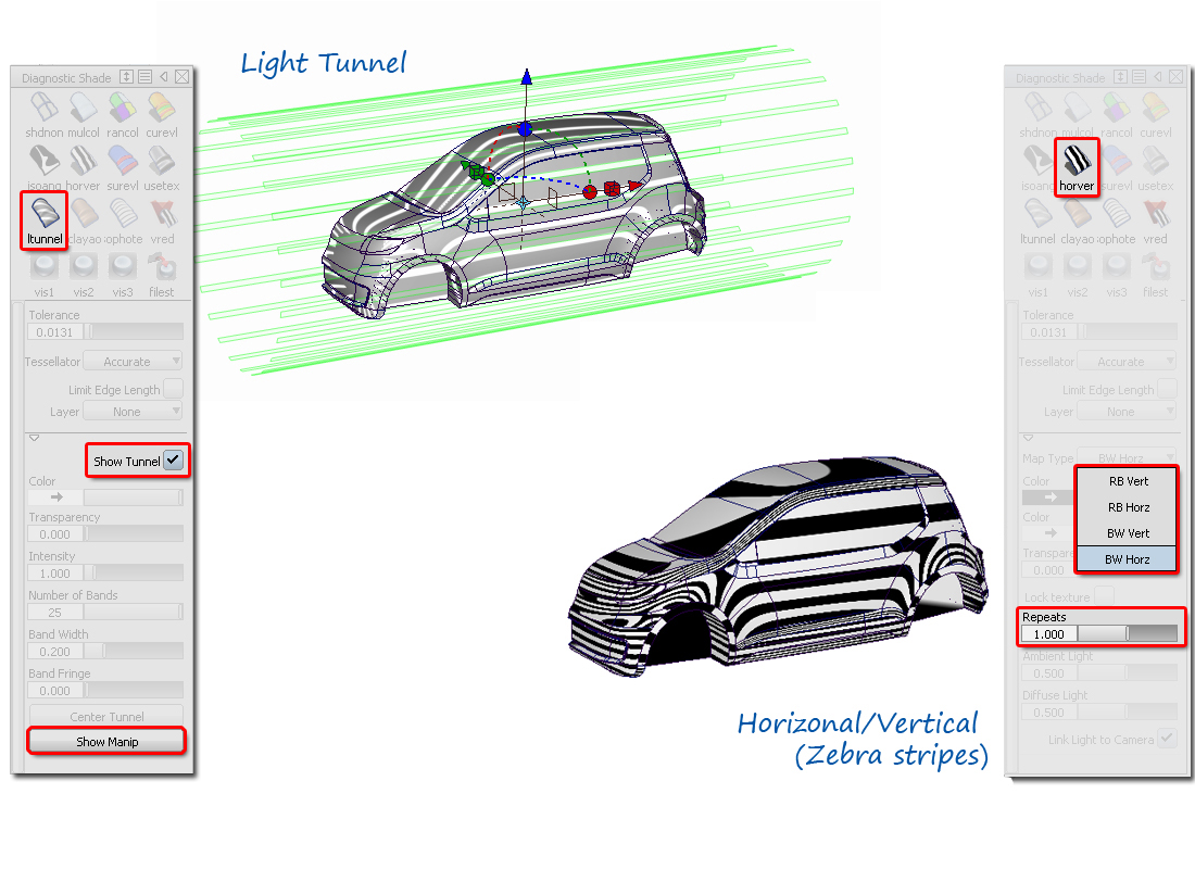
Light Tunnel
- More representative of real-life reflections, but slower to set up and use.
- Reflects a cylindrical Light Tunnel which you can view and manipulate to change the direction and scaling of the 'strip lights'.
- The model and the light tunnel stay in the same position relative to each other as you tumble the view.
Horizontal/Vertical (Zebra stripes)
- Quick to use, and acceptable accuracy for concept development. Mostly used to check continuity between surfaces.
- Reflects a spherical environment with black and white (or rainbow) stripes mapped onto it – which is never visible in the scene. When the view is tumbled, the reflections move across the model and can be positioned where you want to analyse the surfaces.
- The user only has control of the number of stripes (Repeats), and a choice of 'Horiz' and 'Vert' orientation.
- The spherical environment and the eye point are fixed relative to each other. When the view is tumbled, the reflections of the stripes move across the model and can be positioned where you want to analyse the surfaces.
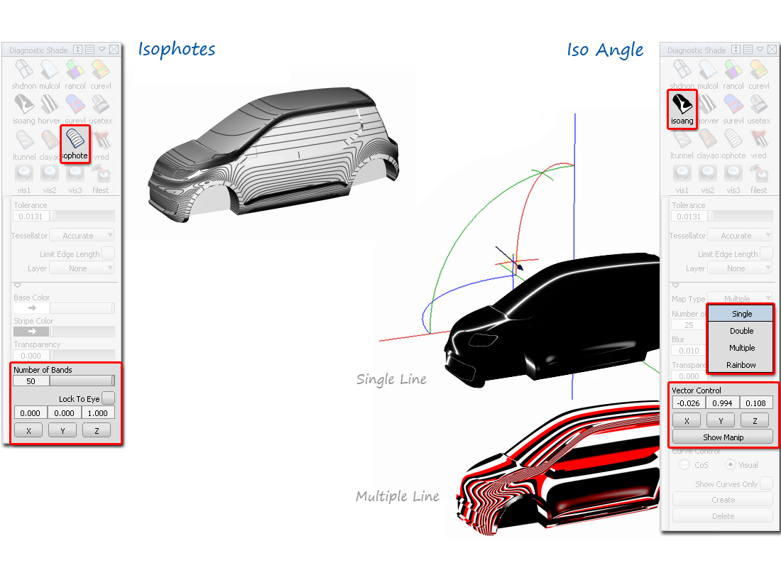
Iso Angle and Iso Curves
Iso Angle and Isophote mean "a line of constant angle". The angle is calculated between the surface normals and a single parallel direction (a vector). Areas of the surface with the same angle to the vector are displayed with a connected iso-line.
It is a more accurate analysis of the reflective properties of the surface than the reflection lines, so should be used when creating high quality production data.
One of the main benefits is that the 'direction' stays in the same orientation to the model, and doesn't change as you tumble the view. This makes evaluations easier to compare and to view in detail.
Again, there are two tools that calculate the evaluation using iso-lines:
Evaluating Continuity between Surface Patches
When evaluating surface joins, the continuity levels are shown by the flow of the stripes:
