Use this procedure to create a custom stair from linework. You can model irregularly shaped stairs and treads, and specify multiple flights at varying angles with a custom stair. You can select or create linework defining stair edges and tread edges. Create a custom stair to model complex existing stair conditions for analysis and explore non-code compliant conditions, or generate stair types that are not possible to create using regular AutoCAD Architecture 2022 toolset stair commands.
The stairs outline component of a custom stair is delineated by the left and right stair sides, the nosing of the first tread, and the front of the last tread or landing.
Stair stringers can be selected as linework, or they can be automatically generated by AutoCAD Architecture 2022 toolset. After you create a custom stair, you can replace stringer paths. You can add or modify stringers by editing the stair style. The stair style applied to the custom stair must have stringers defined in that particular stair style. If the stair style does include stringers, the left and right stringer path lines are converted to appropriate stringer geometry. The current stair properties govern the appearance of stair components in various representations.
Create the linework for your custom stair using lines, light-weight polylines, or arc segments. All tread lines must intersect with the sides of the stair. Graphics representing the stringer paths must be continuous throught the path of the stair.
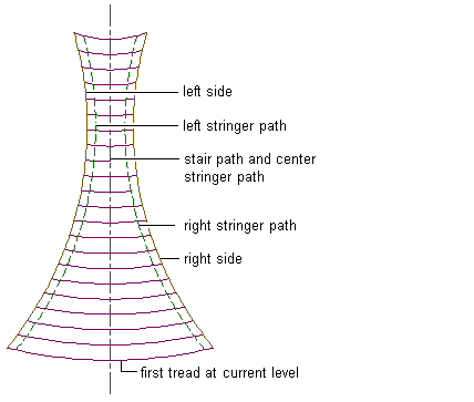
Linework for custom stairs can represent the following components:
- left and right stair sides (required)
- stair path (optional)
- left, right, and center stair stringers (optional)
- first tread at current level (required)
- remaining treads (required) Note: A custom stair must have a minimum of 2 treads. At least 2 lines must be selected for remaining treads when creating a custom stair.
Creating a Custom Stair from Linework
- Open the tool palette that contains the stair tool that you want to use, and select the tool.
You may have to scroll to display the desired tool.
Tip: To ensure that the Properties palette is displayed before you select a tool, click

 Properties.
 - Verify that your current drawing includes a stair style with defined stringers.
- Right-click the stair tool and click Apply Tool Properties to
 Linework.
 - Select the linework that represents the left and right sides of the custom stair.
Only lines, light-weight polylines, or arc segments that intersect all treads can be selected for the stair sides.
- Select the linework that represents the stair path, or press Enter to have it generated automatically.
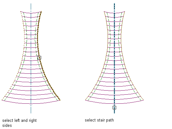
Only single or multi-segment light-weight polylines or arc segments that intersect all treads can be selected for the stair path.
- Select the linework that represents the left, right, and center stair stringers, or press Enter to have the left, right, and center stair stringers generated automatically.
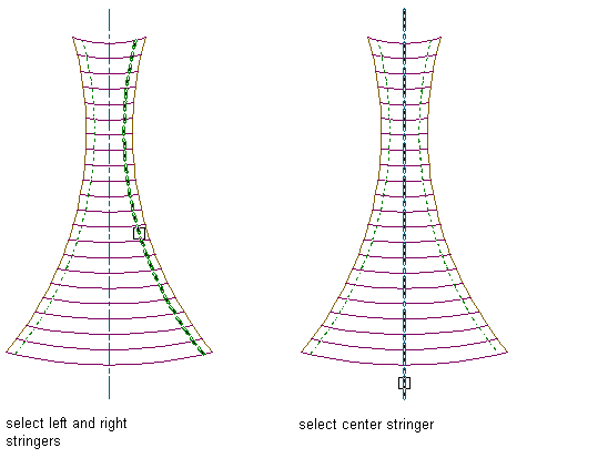
- Select the linework that represents the first tread at the current level.
Only lines, light-weight polylines, or arc segments that intersect the stair sides can be selected for the stair treads.
- Select the remaining treads.
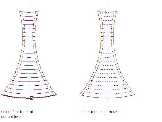
- In the Convert to Stair dialog box, verify or change the parameter values for Style, Height, Vertical Orientation, and Terminate with. Specify a style with defined stringers. Specify whether to erase the layout geometry, then click OK. Note: The Standard stair style does not have defined stringers.
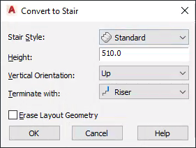 Attention: You cannot convert a custom stair to a ramp stair style.
The custom stair from linework is generated.

Once you create a custom stair, you can convert any part of it to a landing.