Use this procedure to place a callout that creates a 2D section in a new project view drawing.
When you create a section view in a new drawing, the building model is referenced into the new drawing. A 2D section is based on the geometry of the objects cut by the section line. If you place a callout in your First Floor Plan view drawing, and create a 2D section in that drawing, then the section will only contain the first floor geometry - only those building model objects that are present either as drawing objects or external references it the current drawing. When you create a new section view drawing for the 2D section, you can control which levels, divisions, and constructs are included in the section. This affords you enhanced control over what objects will be included in the section. You could, for example, deselect the Furniture construct from the First Floor Plan view drawing, to avoid cluttering up the section with unnecessary building components. In the same way, you can add constructs, levels or divisions not present in the current view drawing, for example, to create background graphics.
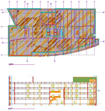
Floor plan (top) and building section (bottom)
- On the Quick Access toolbar, click .

- Click the Views tab.
- Select the view drawing in which you want to place a section callout, right-click, and click Open.
- On the Tool Palettes, click
 (Properties), and click Document.
 - Click the Callouts palette.
- Select a section mark tool.
Alternatively, you can click
 , and select one of the section tools.
 - In the drawing area, specify the first point of the section line.
- Continue to add points to the section line. When you have finished the shape of the section line, press Enter.
- Specify the direction of the section mark arrow.
- Under New Model Space View Name, enter a name for the new model space view containing the section.
- Verify that Generate Section/Elevation is selected.
- If you want to add a title mark to the new model space view, select Place Titlemark.
- Select the scale for the model space view.
- Define the properties of the new view drawing. Note: By default, all constructs, levels, and divisions are preselected here.
- Click Finish.
- In the drawing area, select the insertion point of the generated section. Note: Although you select the insertion point in the current drawing, it will be used in the target drawing where the section result is placed. That way, you have control over the insertion point of the 2D section without opening the target drawing. You can change the location of the 2D section later, when you open the drawing in which the 2D section was placed, and change it there.
Once the model space view has been placed in the new view drawing, the field placeholders in the section callout change to a question mark. To resolve them, the model space view needs to be placed onto a sheet.