Use this procedure to create a structural beam tool and add it to a tool palette.
- Open the tool palette on which you want to add a tool.
- Create the tool:
If you want to… Then… create a tool from a structural member style in the Style Manager click  .
.  Locate the style you want to copy, and drag it to the tool palette. Click OK to close the Style Manager.
 create a tool from a beam in the drawing select the beam, and drag it to the tool palette. copy a tool in the current palette right-click the tool, and click Copy. Right-click, and click Paste. copy a tool from another palette open the other tool palette, right-click the tool, and click Copy. Reopen the palette where you want to add the tool, right-click, and click Paste. copy a tool from the Content Browser open the Content Browser, and locate the tool you want to copy. Position the cursor over the i-drop handle, and drag the tool to the tool palette. - Right-click the new tool, and click Properties.
- Enter a name for the tool.
- Click the setting for Description, enter a description of the tool, and click OK.
The description displays in the tooltip when you select the tool from the tool palette, and describes the tool if you store it in a tool catalog in the Content Browser.
- Expand Basic General.
- Enter a description of the beams that you can create using this beam tool.
- If you do not want to use the layer assignments specified in the layer key style used in the drawing, specify a layer key and any layer key overrides.
- Select a structural member style, and select a style location, if not the current drawing.
The style provides the shape of the beam.
- Specify a value for Bound spaces:
If you want to… Then… allow the beam to be used as a bounding object for associative spaces select Yes. prevent the beam from being used as a bounding object for associative spaces select No. use the bounding setting from the beam style select By Style. - Specify a value for Trim automatically:
If you want… Then… the geometry of the beam to be automatically trimmed to any other structural members, other architectural objects, or linework to which it is logically connected select Yes. prevent the geometry of the beam from being trimmed automatically select No. use the trim setting from the beam style select By Style. Note: This setting affects only the structural member being added. Adding a new structural member will not change the geometry of an existing structural member, regardless of the setting for Trim automatically. - Expand Dimensions.
- Specify offsets:
If you want to… Then… offset the beam on its extruded axis at the start point of the beam enter a value for Start offset. A positive value shortens the beam on its axis, while a negative value lengthens the beam on its axis. offset the beam on its extruded axis at the endpoint of the beam enter a value for End offset. A positive value lengthens the beam on its axis, while a negative value shortens the beam on its axis. - Enter a value for Roll.
This value specifies the orientation of the beam relative to its extruded axis in terms of degrees of roll. A positive value rolls the beam counterclockwise when viewed from its end to its start.
- If Layout type is Fill, and you want beams to be added to the selected edge of a column grid, slab, roof slab, or wall at an angle other than the default of 90 degrees, enter a value for Angle relative to selected object.
- Select a Layout type to specify how a beam is positioned in relation to a highlighted edge of a column grid, slab, roof slab, or wall:
If you want to position the beam… Then… along the highlighted edge of the object select Edge for Layout type. within the boundaries of the object (from one edge to an opposite edge or edges) select Fill for Layout type. - Specify the beam justification, which positions the beam shape in relation to its extruded axis when you draw the beam:
If you want to… Then… position the axis of the beam along the centroid of the beam shape select Baseline for Justify. Note: This applies to members created with styles from the Structural Member Catalog only.position the axis of the beam along one of 9 positions on the beam shape select one of the 9 positions for Justify. Note: These positions are defined at a roll of zero, viewing the beam from the end to the start.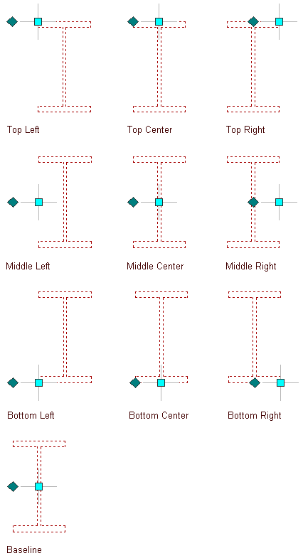
Justification options for a beam
- To specify the justification of members with multiple shapes and segments created with this tool, select a setting for Justify using overall extents:
If you want to justify the member… Then… based on the largest cross-sectional extent of the member’s lowest priority shapes select Yes. The justification is applied ONLY to the lowest priority shape definitions, and is calculated based on the node (vertex) of the member with the greatest cross section. at each node, based on all shapes select No. The justification is calculated based on the cross-sectional extents at each node, and applied to all the shapes without regard to priority. - If Layout type is Fill, and you want to array multiple beams between two existing beams or within a column grid, slab, roof slab, or wall, expand Layout and select Yes for Array.
- Specify the layout method for the array:
If you want to array beams… Then… so that they create a specific number of equal-sized bays select Space evenly for Layout method, and enter a value for Number of bays. at a specific distance from each other select Repeat for Layout method, and enter a value for Bay size. - Click OK.