Refer to the illustrations and steps in this topic to use grips to edit structural members.
Editing Structural Member Dimensions
- Select the structural member.
- Select the grip for the dimension you want to change.
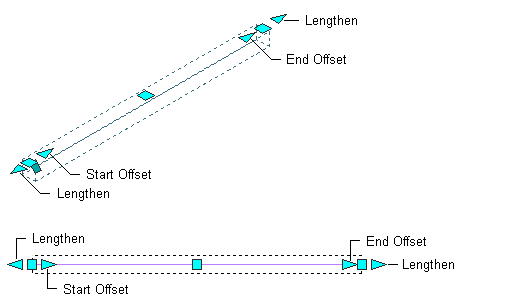
Grips for length, start offset, and end offset of a straight beam or brace
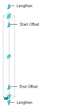
Grips for length, start offset, and end offset of a straight column
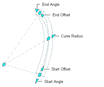
Grips for start and end angles, radius, and start and end offsets of a curved beam or brace

Grips for start and end angles, radius, and start and end offsets of a curved column
- Move the grip until the dimension value you want is displayed, and click once; or enter a value.
Changing the Location of a Structural Member
- Select the structural member.
Select the Location grip to change the location of the structural member, or the Roll grip to change its roll (the rotation of the member around its extruded axis).
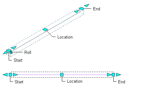
Location and roll grips for a straight beam or brace
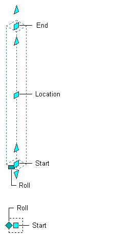
Location and roll grips for a straight column
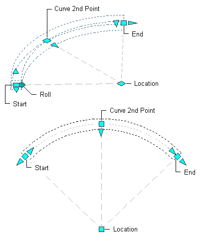
Location and roll grips for a curved beam or brace
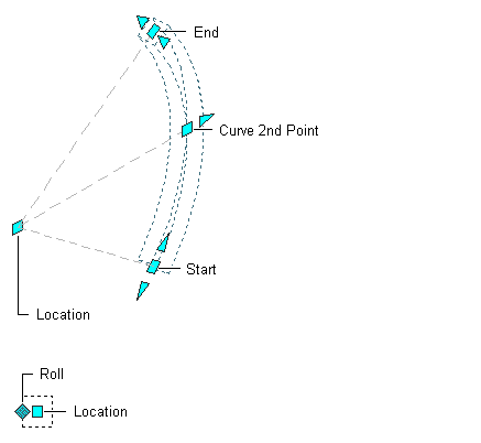
Location and roll grips for a curved column
In Model view, the Location grip has six edit options you can cycle through by pressing Ctrl. For each plane in which you can move the member (XY, YZ, or XZ), you have the option of maintaining or breaking connections with other structural members.
When you choose to maintain connections, all connections are not necessarily maintained for every type of move. Maintenance of connections depends on whether the move is in or out of plane, how the members are connected, and which type of members are involved. Generally, columns take precedence over beams and braces in determining how connected members behave when one is moved. This behavior is summarized in the following table:
If you specify Maintain Connections when moving … Then … a column other columns, beams, and braces connected to an endpoint of the column will also move, changing length and orientation as necessary to maintain the connection. (This is also true for any other members connected along the length of a member that is endpoint-connected to the column.) Structural members connected along the length of the column will only extend or shorten to remain connected; they will not change orientation unless the column is moved out of plane. For example, if a column is moved in the XY plane, beams or braces connected along its length will stay connected, even though their orientation changes. a beam or a brace other beams and braces connected to an endpoint of the beam or brace will also move, changing length and orientation as necessary to maintain the connection. Structural members connected along the length of the beam or brace will only extend or shorten to remain connected; they will not change orientation unless the beam is moved out of plane. For example, if a ridge beam is moved vertically, rafters connected along its length will stay connected, even though their orientation changes. The default edit mode is to maintain connections for moves along the XY plane. In Plan view, the Location grip is restricted to movement in one plane, but you still have the option to maintain or break connections.
- Move the grip until the dimension value you want is displayed, and click once; or enter a value and press Enter.
If you want to enter a specific value for the second direction in any edit mode (for example, in the Y direction when editing along the XY plane), press Tab to cycle to the second direction.
You can also lock the movement of the structural member along a specific direction. If you enter a value for either of the dimension directions in the current edit mode and then press Tab, the movement of the structural member is constrained to the second dimension direction. When editing along the XY plane, for example, you can enter a value for X dimension, and then press Tab. The X dimension is locked at that value, and movement of the structural member is constrained to the Y dimension direction.
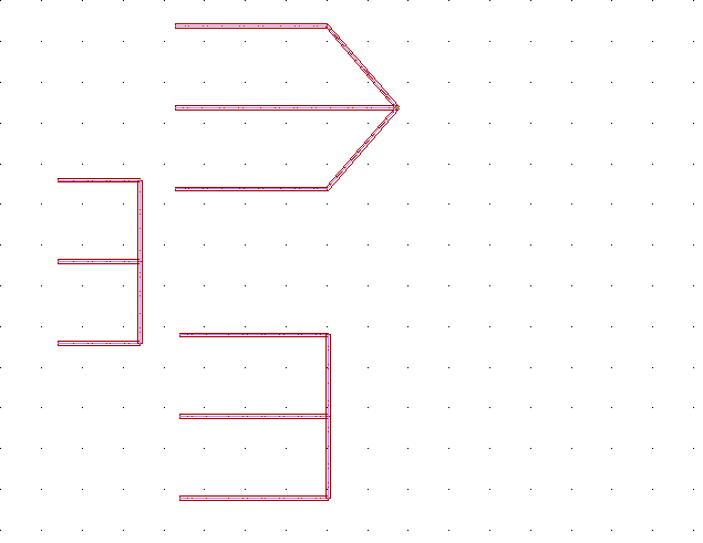
- Right-click, and click Deselect All to turn off grips. Note: When you shift-select the Location grips of end-connected beams, the common endpoint moves approximately twice as far as the grip you move. In the example shown below, if you shift-select the two vertical beams in the structure on the left, and then move a grip toward the right, the result is a configuration like the one at the top right. To get a configuration like the one at the bottom right, you would select all five beams using a crossing selection or a crossing polygon, and then use the STRETCH command. Beams may also move twice as far as you might expect when they are attached to columns on a column grid, and the grid, columns, and beams are all selected. If you select and move only the grid, the columns and beams will move with it, maintaining their same relative positions.
