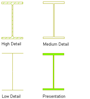
Structural member geometry is created by a shape contained in the style of the structural member that is extruded along the axis of the member. Each shape can have different levels of detail in its geometry, allowing different displays of the structural member that the shape is defining. If you look at the display representations of a structural member, you see that there may be more than one of the same representation. Each representation displays the structural shape in a different level of detail.
For example, you can use the Plan, Plan High Detail, and Plan Low Detail structural member representations to display a plan view of a structural member.

Displaying a structural member with the Plan High Detail, Plan Low Detail, and Plan display representations
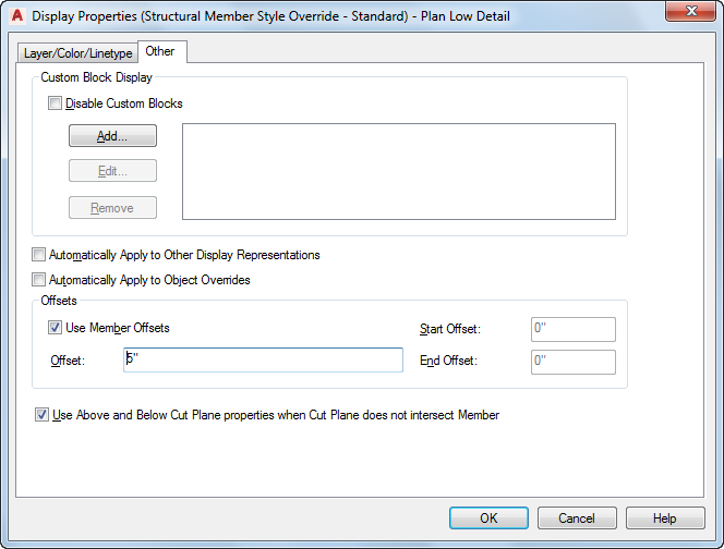
The Plan Low Detail display representation displays the member with simple lines and arcs. You can use this display representation to create a top view framing plan where you want a single line representation of a column. The Plan Low Detail display representation includes two display components, Beam Sketch and Brace Sketch. You can change the display properties of these components, such as layer, color, and linetype, to differentiate the display of beams and braces. On the Other tab of the style override dialog box for this display representation, you can also add offsets between members to display them as you typically would in a top view framing plan. Note that the Use Member Offsets check box applies only to the start and end offsets. The Offset value below the check box applies only to structural braces, and allows you to offset them horizontally so that they are visible even when positioned directly underneath a beam.

The Plan and Plan High Detail display representations display the previous column using closed polylines. Both representations display the column geometry, but the Plan High Detail representation is more detailed, including fillets in the column display. Use the Plan representation to improve performance while modeling, and the Plan High Detail representation to display an added level of detail for detail drawings.
The following table lists the structural member display representations and their uses:
| Use this display representation… | To… |
|---|---|
| Elevation | display an elevation view of a structural member with simplified geometry for better performance when modeling. |
| Elevation High Detail | display an elevation view of a structural member in full detail. |
| Logical | display the extruded axis of a structural member and connections between members. Connections are automatically established between members when they touch endpoint to endpoint or endpoint to a point on the extruded axis of another member. |
| Model | display a 3D structural member with simplified geometry for better performance when modeling. |
| Model High Detail | display a 3D structural member in full detail for large scale details. |
| Plan | display a 2D structural member in less detail than the Plan High Detail representation to improve performance. Members display as closed polylines, rather than lines and arcs as in the Plan Low Detail representation. |
| Plan High Detail | display a 2D structural member in full detail. |
| Plan Low Detail | display a 2D structural member with simple lines and arcs to create a top view framing plan. Includes a Beam Sketch and Brace Sketch display component to differentiate beams and braces in plan view. |
| Plan Presentation | display a 2D structural member with solid hatching (poche) for plan view presentation drawings. |
| Plan Screened | display a 2D structural member in the screened portion of a screened floor plan, with components and hatching visibly lighter than some other objects. |
| Reflected | display a 2D structural member in a reflected ceiling plan. |
| Reflected Screened | display a 2D structural member in the screened portion of a screened reflected ceiling plan with components and hatching visibly lighter than some other objects. |