Use this procedure to specify the display of stair components in plan view depending on their occurrence above or below the cut plane elevation. You can specify the above cut plane, up, and down component properties for each type of stair component.
Cut Plane Elevation Display Properties
-
Take a look at the display properties for these kinds of stair components.
Select the stair and click

 .
. 
- Click the Display Properties tab.
- Verify that Plan is the default Display Representation, and then click
 (Edit Display Properties).
 - Click the Layer/Color/Linetype tab.
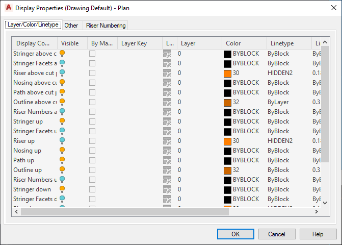
There are components to support the representation of stair components above the cut plane elevation so that the down stair components are only used to display the stair components that occur below the current level.
- Click the Other tab.
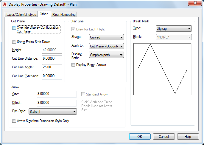
For stairs created in versions of Autodesk Architectural Desktop earlier than 2004, the Override Display Configuration Cut Plane option is selected by default. In the current version, this option is cleared by default, and the display of stair components is handled automatically by specific display configurations for each level.
When the Override Display Configuration Cut Plane option is selected, the cut height elevation is measured from the bottom of each stair run. The up display components and the above cut plane display components above the current level are displayed, and the down display components are not.
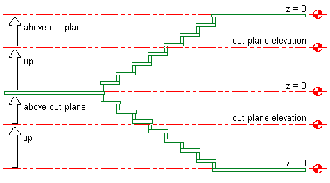
Specifying cut plane elevation with display configuration override
When the Override Display Configuration Cut Plane option is cleared, the cut height elevation is measured from the current level. The up display components above the current level are displayed, as are the down display components below the current level.
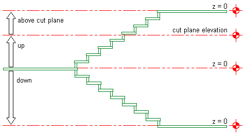
Specifying cut plane elevation without display configuration override
- Make changes to the display of stair components as needed, then click OK twice.
Specifying Stair Display at Different Levels
-
The following procedure provides an example of how to specify the display of stair components at different levels in a stair tower.
Create a U-shaped stair, 5’-0” (1520 mm) wide and 12’-0” (3650 mm) high to represent the lobby stairs. - Create a second U-shaped stair, 3’-8” (1120 mm) wide and 10’-0” (3050 mm) high, and locate it 12’-0” (1520 mm) above the lobby stairs.
- Create a third U-shaped stair, 3’-8” (1120 mm) wide and 10’-0” (3050 mm) high, and locate it 10’-0” (3050 mm) above the second set of stairs.
The following illustration shows how the stair tower should appear with added floor slabs in a 3D view:
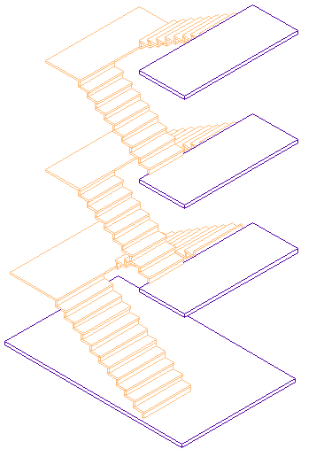
3D view of stair tower
- Save this stair tower configuration as the base stair drawing file.
- Create 4 new host drawing files as follows:
- First Floor
- Second Floor
- Third Floor
- Roof Level
The following illustration shows how the levels should appear in an elevation view:
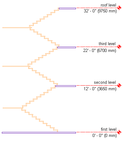
Elevation view of stair tower
- Open the First Floor drawing, and attach the base stair as an Xref at an elevation of 0’-0” (0 mm).
- Verify that the Medium Detail display configuration is current.
- View the first floor lobby stairs in plan.
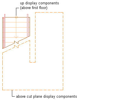
Stair display components at first floor
-
The up display components above the first floor are displayed, as are the above cut plane display components, in outline with a dashed linetype.
- Open the Second Floor drawing, and attach the base stair as an Xref at an elevation of -12’-0” (-3650 mm).
- Verify that the Medium Detail Intermediate Level display configuration is current.
- View the second floor stairs in plan.
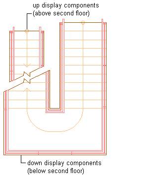
Stair display components at second floor
-
The up display components above the second floor are displayed, as are the down display components below the second floor.
- Open the Third Floor drawing, and attach the base stair as an Xref at an elevation of -22’-0” (-6700 mm).
- Verify that the Medium Detail Intermediate Level display configuration is current.
- View the third floor stairs in plan.
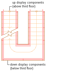
Stair display components at third floor
-
The up display components above the third floor are displayed, as are the down display components below the third floor.
- Open the Roof Level drawing, and attach the base stair as an Xref at an elevation of -32’-0” (-9750 mm).
- Verify that the Medium Detail Top Level display configuration is current.
- View the roof level stairs in plan.
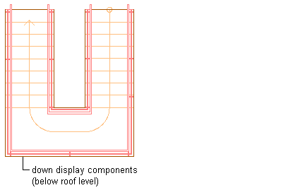
Stair display components at roof level
-
Only the down display components below the roof level are displayed.