Walls are more complex objects and affected by a variety of styles and substyles. When a wall style that references a specific substyle is imported into a drawing, it will import all necessary substyles with it.
Wall Styles
Naming Conventions
You should provide as much information about the wall structure in the name itself as practical. This makes it easier to discriminate between wall styles in a long list without having to refer to the wall style description. The first component listed is the major structural component. The last component listed is usually a finish component.
<Component name>-<Size in decimal units> <Component name>-<Size in decimal units>...
Example Wall Style Names:
| Wall Style Description | Example Name |
|---|---|
| Wall structure: 5/8” gypboard interior finish, 3 1/2” wood stud, 1/2” sheathing, 1” air gap and 3 5/8” brick veneer. | Stud-3.5 Brick-3.625 Sheathing-0.5 Air-1 GWB-0.625 |
| Wall structure: 5/8” Gypboard interior finish on both sides of a 3 1/2” wood stud. | Stud-3.5 GWB-0.625 Both Sides |
| Wall structure: 5/8” Gypboard interior finish on both sides of a variable width wood stud. | Stud-X GWB-0.625 Both Sides |
Best practices for wall styles
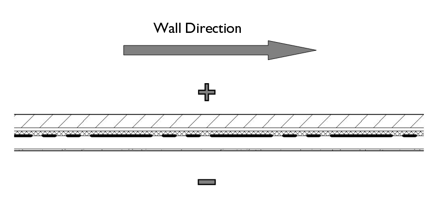
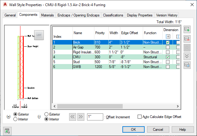
- Walls are directional and should be considered as having an exterior and interior side. The exterior, or positive side of the wall, is at the top of a wall running left to right. Wall components should be defined so that the index order is from exterior to interior. The component furthest to the exterior side of the wall should have an index assignment of 1, while the most interior component will have the highest index assignment.

- When specifying the edge offset of a component, the value should always be to the most interior edge of the component.
- The width of components is always a positive value.
- Wall priorities should be standardized and based on the existing AutoCAD Architecture 2022 toolset convention.
- Materials should be assigned to all wall components.
- Plan display of wall components should normally be set to observe the drawing default settings. Best practice is to assign materials to wall components and set their linework and hatch pattern parameters to By Material in the plan display settings. Note: Prior to the introduction of material definitions in Architectural Desktop 2004 it was common and recommended practice to assign wall style components to nested layers and set their color, line type, line weight, and plot style settings to BYLAYER. While this is still technically valid in AutoCAD Architecture 2022 toolset, it is not recommended except for a very few exceptions (such as the Plan Screened display representation, which is frequently used to export plan displays to consultants using AutoCAD, who desire the items to be on a prescribed layer and assigned colors appropriate for background drawings).
- Model display of wall components should be set to the drawing defaults to allow for material assignments to control the color and hatching of walls when viewed in non-orthogonal views.
- Wall styles should be classified. This allows for more flexible scheduling and tagging in the future, as well as more display control options. Note: The Uniformat II classification definition is supplied in the Uniformat II Classifications (1997 ed).dwg file located in the AEC ContentStyles path. This classification definition is fairly comprehensive and in many cases serves well in classifying all types of AutoCAD Architecture 2022 toolset object styles according to a uniform standard.
- Walls that have one or more obvious internal dimension points (such as the outside of a structural component) should have those specified in the wall style Components Tab under the Dimensions column. This allows for more accurate application of AEC dimensions.
- Wall components should be assigned a “Structural” or “Non-Structural” designation under the “Type” column in the “Components” Tab, again to allow for more effective use of AEC dimensions.
- Walls should have an interior and exterior side specified as part of the wall style definition to ensure more accurate AEC Dimensioning.

To ensure accurate dimensioning with AEC dimensions, the wall in the following image has had its components assigned to either “Structural” or “Non-Structural” types. Dimension points and the exterior/interior sides of the wall are also specified.
Wall Endcap Styles
Wall endcap styles are intended to be used with specific wall styles. They can be used to define actual end conditions as well as opening conditions as part of a Wall Opening Endcap Style.
Naming Conventions:
Wall endcap styles should be named according to the wall style to which they apply, with an indication of the condition they are meant to address:
<Associated wall styles> (<End condition><Index>)
Example Wall Endcap Style Names:
| Wall Endcap Style Description | Example Name |
|---|---|
| For wall style Stud-3.5 Brick-3.625 Sheathing-0.5 Air-1 GWB-0.625 to define the first end condition. | Stud-3.5 Brick-3.625 Sheathing-0.5 Air-1 GWB-0.625 (End1) |
| For wall style Stud-3.5 Brick-3.625 Sheathing-0.5 Air-1 GWB-0.625 to define a possible second end condition. | Stud-3.5 Brick-3.625 Sheathing-0.5 Air-1 GWB-0.625 (End2) |
| or wall style Stud-3.5 Brick-3.625 Sheathing-0.5 Air-1 GWB-0.625 to define a jamb condition. | Stud-3.5 Brick-3.625 Sheathing-0.5 Air-1 GWB-0.625 (Jamb1) |
Best Practices for Wall Endcaps:
- Endcaps are drawn for each component. Components for which there is no endcap defined will terminate as soon as another component’s endcap is encountered. For that reason, you need to draw a complete endcap for each component except for those that are intended to terminate at the location on the wall where the endcap is applied.
- Endcaps are applied perpendicular to the direction of the wall. The endpoints of each endcap are normally drawn so that an imaginary line connecting them would be perpendicular to the wall edges, except in the case where an endcap is intentionally skewed.
- It is typically not recommended to define endcaps for walls with variable width components. As a component’s width is changed, its associated endcap will adjust to accommodate the change in width, however the endcap will maintain its proportions, causing distortions to occur to the end effect.
Wall Opening Endcap Styles
Wall Opening Endcap Styles apply to door, window, opening and door/window assemblies that are inserted into a wall. They consist of a collection of wall endcap styles that are applied to the head, jamb and sill conditions of the opening.
Wall Opening Endcap Style Naming Conventions:
The naming convention for a wall opening endcap style is similar to that for a wall endcap style:
<Associated wall style> (Opening<Index>)
Example Wall Opening Endcap Style Names:
| Wall Opening Endcap Style Description | Example Name |
|---|---|
| Wall opening endcap style for a wall style named Stud-3.5 Brick-3.625 Sheathing-0.5 Air-1 GWB-0.625. | Stud-3.5 Brick-3.625 Sheathing-0.5 Air-1 GWB-0.625 (Opening1) |
Wall Cleanup Group Definitions
Wall Cleanup Group definitions should allow objects anchored to walls in other cleanup groups to be moved or copied to walls of the current cleanup group unless there is a compelling reason to not allow it. Cleanup between host and xref drawings should be turned on by default unless performance issues arise. There are no naming conventions for wall cleanup group definitions.
Wall Modifier Styles
Wall modifiers are typically best created “on the fly” by first creating a 2D polyline and converting it to a wall modifier. During the process you are prompted for a name to assign to a new modifier style, which is created from your geometry. Modifier styles define minimal information about the shape of the modifier itself. There are no current conventions for naming or application of wall modifier styles.
Palette-Based Wall Tools
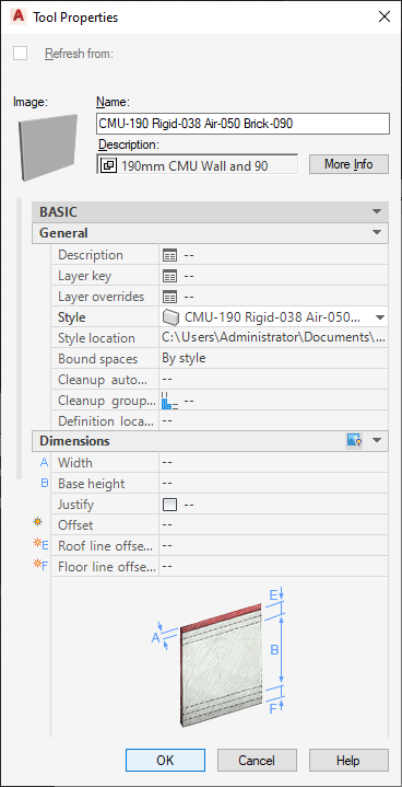
The only wall-based style that can be assigned to a palette-based tool is the wall style itself. However when the wall style is used, any substyles that it uses, such as wall endcap styles and wall opening endcap styles, will be imported with it automatically. Additionally there are some tool properties that you may want to consider setting as defaults before saving the tool to a catalog:
- Justification: In the case of exterior walls, the baseline is usually defined at a critical dimensional location within the wall structure. In these cases it is a good idea to pre-set the justification property of the tool to “Baseline”.
- Cleanup Group Definition: If you have defined a wall that should not clean up with other walls that are not of the same type, you can pre-set the cleanup group definition that it is inserted with. Attention: To pre-set the wall cleanup group definition, you must first specify the library drawing in which the cleanup group definition exists, then define the cleanup group to use. Even if the cleanup group already exists in the current drawing, it will not be used unless you specify the definition location.

Wall tool pre-sets to establish the default cleanup group definition and the justification.