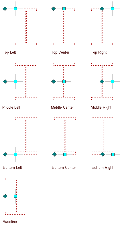
Use this procedure to change the justification of a structural member. Justification positions the shape of a structural member in relation to its extruded axis. Changing the justification of an existing member moves the member and can affect how the member relates to other objects, such as how a column is positioned in relation to a column grid when it is anchored to the grid.

Justification options for a beam
You can also specify the justification of structural members with multiple shapes and segments.
- Select the structural member to change, and double-click it.
- On the Properties palette, expand Basic, and expand Dimensions.
- Select a setting for Justification:
If you want to… Then… position the axis of the member along the centroid of the member shape select Baseline for Justify. Note: This applies to members created with styles from the Structural Member Catalog only.position the axis of the member along one of 9 positions on the member shape select one of the 9 positions for Justify. - To specify the justification of members with multiple shapes and segments created with this tool, select a setting for Justify using overall extents:
If you want to… Then… justify the member based on the largest cross-sectional extent of the member’s lowest priority shapes select Yes. The justification is applied ONLY to the lowest priority shape definitions, and is calculated based on the node (vertex) of the member with the greatest cross section. justify the member at each node, based on all shapes. select No. The justification is calculated based on the cross-sectional extents at each node, and is applied to all the shapes without regard to priority.