In AutoCAD Architecture 2022 toolset, dimensional and geometric constraints can be applied to AEC objects when you are working in a 2D plan view. AEC object constraints are enhanced versions of the AutoCAD constraints, providing you with additional functionality in the interaction between AEC objects. In general, AEC object constraints support initial object entity selection rather than point selection.
The following AEC objects support constraints:
- Walls
- Column grids
- Columns
- Beams
- Curtain walls
- Mass elements
- Multi-view blocks
Examples of the use of constraints for AEC objects include constraining exterior walls to a column grid using Fix and Horizontal constraints, aligning the centerline of a curtain wall with a column grid using the Aligned constraint, and anchoring 2 column grids together with the Coincident constraint.
The following AEC object constraints can be applied to the appropriate AEC objects:
| Geometric Constraints | Dimensional Constraints |
|---|---|
| Coincident | Aligned |
| Vertical | Angular |
| Collinear | Radial |
| Horizontal | Distance |
| Fix | Diameter |
| Parallel | |
| Perpendicular | |
| Concentric | |
| Symmetric | |
| Tangent | |
| Equal | |
| Smooth |
All of the AutoCAD constraints are supported by the appropriate AEC objects, but the AUTOCONSTRAINT and Infer Constraints features are not.
With a grip selected or when you specify options during an editing command, tap the Shift key to alternate between relaxing constraints and maintaining constraints.
When you select one of the AEC objects that support constraints, the Parametric panel on the contextual ribbon tab displays the constraints available for the selected object.

Parametric panel
Different AEC objects have different selection options when working with AEC object constraints. The Coincident and Fix constraints are point constraints only, but the other AEC object constraints allow you to select various object entities to constrain.
For example, you can pick
- either edge or the centerline of a wall segment to constrain.
- the object edge, X or Y axis, or bounding box edge of a mass element to constrain.
- the object edge, centroid, or bounding box edge of a structural member to constrain.
As you select the AEC object to constrain, press Tab to cycle through your options. Valid selectable object entities are highlighted with a red line.
Working with the Coincident constraint
- Select a column grid.
- Click

 .
. - Select a corner point on the first column grid to constrain.
The selected point is shown with a red circle and X through its center.
- Select a corresponding corner point on the second column grid to constrain.
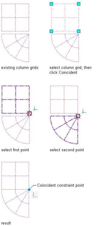
When you move one of the column grids, the other one moves with it. You can also rotate one of the column grids about the Coincident constraint point. To fully constrain both grids, add another Coincident constraint to the other column grid corner.
The Coincident constraint constrains 2 points to coincide. The constrained points can lie directly on an AEC object, or the extension of an AEC object. The Coincident constraint also works between appropriate AEC objects and AutoCAD objects, such as a wall segment and a line.
Use a Coincident constraint to anchor 2 column grids together.
Working with the Vertical Constraint
- Select the curtain wall segment.
- Click
 .
. - Specify a point on the curtain wall segment near the end that you want to remain fixed.
The curtain wall segment end closest to the specified point becomes the pivot point.

The Vertical constraint constrains lines or pairs of points on AEC objects to lie parallel to the Y-axis of the current UCS. When you specify 2 points to vertically constrain, the second point is made vertical to the first point.
Use a Vertical constraint to realign a curtain wall segment vertically.
Working with the Collinear Constraint
- Select the column grid.
- Click
 .
. - Hover your cursor over the column grid line.
The grid line is highlighted with a red line.
- Select the red grid line.
- Hover your cursor over the edge of the wall segment.
The wall segment edge is highlighted with a red line.
- Press Tab to highlight the wall centerline.
The wall segment centerline is highlighted with a red line.
- Select the wall segment.

The Collinear constraint aligns one AEC object with another. The second selected AEC object is made collinear with the first selected AEC object. You can align edges or centerlines of AEC objects as necessary. The Collinear constraint also works between appropriate AEC objects and AutoCAD objects, such as a column grid and a line.
Use a Collinear constraint to align the centerline of a wall with a column grid line.
- Select the mass element.
- Click .
- Hover your cursor over the edge of the mass element.
The top edge of the mass element is highlighted with a red line.
- Press Tab to highlight the mass element X and Y axes.
The X axis is highlighted with a red line.
- Press Tab to highlight the mass element bounding box.
The right bounding box line is highlighted with a red line.
- Select the top bounding box line of the mass element.
- Select the bottom edge of the wall segment.

Use a Collinear constraint to align the edge of a mass element with the edge of a wall segment.
Working with the Horizontal Constraint
- Select the wall segment.
- Click
 .
. - Specify a point on the wall segment near the end that you want to remain fixed.
The wall segment end closest to the specified point becomes the pivot point.

The Horizontal constraint constrains lines or pairs of points on AEC objects to lie parallel to the X-axis of the current UCS. When you specify 2 points to horizontally constrain, the second point is made horizontal to the first point.
Use a Horizontal constraint to realign a wall segment horizontally.
Working with the Fix Constraint
- Select the column.
- Click
 .
. - Select the column to constrain.
The column is fixed in place and cannot be moved or rotated.
The Fix constraint is a point constraint that maintains the position of an AEC object in your drawing.
Use a Fix constraint to maintain the position of a structural member.
Working with the Aligned Constraint
- Select the multi-view block.
- Click
 .
. - Select the edge of the multi-view block.
- Select the edge of the wall segment.
- Specify the dimension location.
- Enter a new dimension value.

When you move either AEC object, the specified distance between them is maintained.
The Aligned constraint maintains the distance between 2 parallel elements on 2 different AEC objects.
Use an Aligned constraint to maintain a specific distance between a wall segment and a multi-view block.
Working with the Angular Constraint
- Select the wall segment.
- Click
 .
. - Select the first wall segment edge as the angle baseline.
- Select the second wall segment edge to constrain.
- Specify an angle location.
- Enter a new angle value.

When you move either AEC object, the specified angle between them is maintained.
The Angular constraint maintains a specific angle between 2 AEC objects. The Angular constraint also works between appropriate AEC objects and AutoCAD objects, such as a wall segment and a line.
Use an Angular constraint to maintain an angle between 2 attached wall segments.
Working with the Radial Constraint
- Select the arc wall segment.
- Click
 .
. - Select the arc wall segment edge.
- Specify the radius location.
- Enter a new radius value.

The Radial constraint maintains a specific radius of an AEC object. The Radial constraint also works between appropriate AEC objects and AutoCAD objects, such as a wall segment and a line.
Use a Radial constraint to maintain the radius of an arc wall segment.