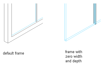
Use this procedure to define a frame by specifying its width and depth. The overall frame size is determined by the length and height of the door/window assembly grid.
Because door/window assemblies can contain multiple styles with different frames, it is helpful to use a naming convention for grid frames that indicates the grid location or purpose within the door/window assembly. For example, L3-FL1- Metal Frame identifies a metal frame in a third-level grid on Floor 1.
Tip: To remove the frame edge and have the infill adjust to fill the space occupied by the frame, create a frame definition with both width and depth set to zero. Then assign that definition to the frame edge that you want to remove. This is necessary for the infill to be mitered as it would be for a butt-glazed condition.

Specifying a Door/Window Assembly frame width and depth of zero
- Click

 .
. 
- Expand Architectural Objects
 Door/Window Assembly Styles. Note: Alternatively, select a door/window assembly in the drawing, and click

 .
. 
- Select a door/window assembly style.
- Click the Design Rules tab.
- In the left pane, select Frames under Element Definitions.
- Click
 to create a new frame definition.
 - Enter a descriptive name for the frame.
- Specify a width and depth for the frame.
- Specify any offsets.
- Click OK.
After you create a frame definition, you can assign it to any frame in a door/window assembly.