Use this procedure to create a custom shape for a structural member based on linework you have drawn or otherwise inserted in the drawing area.
- In the drawing area, create three geometries to define the Plan Low Detail, Plan, and Plan High Detail display representations of the shape. You can draw entirely new geometries, or you can insert geometries from existing shape definitions.
For Plan Low Detail, you can use lines, arcs, circles, or polylines. For Plan and Plan High Detail, use closed polylines, splines, ellipses, or circles. Note that these entities must not intersect.
- Select a structural member.
- Click

 .
. 
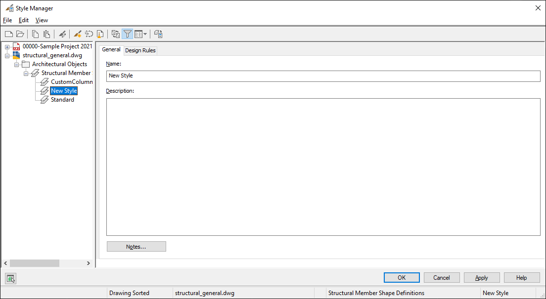
The Style Manager is displayed with the Architectural Objects folder open and Structural Member Shape Definitions selected.
- Right-click Structural Member Shape Definitions, and click New
- In the right pane of the Style Manager, click the General tab.

- Enter a name and description for the new shape, and then click the Design Rules tab.
- For Shape Geometry, select Low Detail, and then click
 .
. - In the drawing area, select the line(s), arc(s), circle(s), or polyline(s) to define the Plan Low Detail display representation for the new shape, and then press Enter.
- Select an insertion point.
The low detail shape is displayed in the viewer under the Design Rules tab.
- For Shape Geometry, select Medium Detail, and then click
 .
. - In the drawing area, select a closed polyline, spline, ellipse, or circle to define the Plan display representation for the selected shape designation.
- Select an insertion point, or enter c (Centroid) or p (Previous Point) to position the selected shape in the viewer.
- For Shape Geometry, select High Detail, and then click
 .
. - In the drawing area, select a closed polyline, spline, ellipse, or circle to define the Plan High Detail display representation for the shape.
- Select an insertion point, or enter c (Centroid) or p (Previous Point) to position the selected shape in the viewer.
- If you want to create a new structural member style from the shape, click
 , enter a name for the new style, and click OK.
 - Click OK to add the new shape to the list of Structural Member Shape Definitions and dismiss the Style Manager.
The new shape can now be added to existing structural member styles.