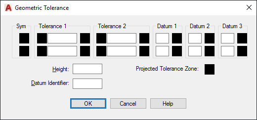
Specifies the symbols and values for a feature control frame.
TOLERANCE (Command) Find
After you select geometric characteristic symbols, the Geometric Tolerance dialog box closes and the following prompt is displayed:
Enter tolerance location: Specify a location
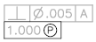
The feature control frame is placed at the specified location.
List of Options
The following options are displayed.
Sym
Displays the geometric characteristic symbol, which you select from the Symbol dialog box. The dialog box is displayed when you select one of the Sym boxes.
Tolerance 1
Creates the first tolerance value in the feature control frame. The tolerance value indicates the amount by which the geometric characteristic can deviate from a perfect form. You can insert a diameter symbol before the tolerance value and a material condition symbol after it.
- First Box
-
Inserts a diameter symbol in front of the tolerance value. Click the box to insert the diameter symbol.
- Second Box
-
Creates the tolerance value. Enter a value in the box.
- Third Box
-
Displays the Material Condition dialog box, in which you select a modifying symbol. These symbols act as modifiers to the geometric characteristic and the tolerance value of features that can vary in size.
The symbol is inserted into the MC box for the first tolerance value in the Geometric Tolerance dialog box.
Tolerance 2
Creates the second tolerance value in the feature control frame. Specify the second tolerance value in the same way as the first.
Datum 1
Creates the primary datum reference in the feature control frame. The datum reference can consist of a value and a modifying symbol. A datum is a theoretically exact geometric reference used to establish the tolerance zone for a feature.
- First Box
-
Creates the datum reference value.
- Second Box
-
Displays the Material Condition dialog box, in which you select a modifying symbol. These symbols act as modifiers to the datum reference.
The symbol is inserted into the MC box for the primary datum reference in the Geometric Tolerance dialog box.
Datum 2
Creates the secondary datum reference in the feature control frame in the same way as the primary datum reference.
Datum 3
Creates the tertiary datum reference in the feature control frame in the same way as the primary datum reference.
Height
Creates a projected tolerance zone value in the feature control frame. A projected tolerance zone controls the variation in height of the extended portion of a fixed perpendicular part and refines the tolerance to that specified by positional tolerances.
Projected Tolerance Zone
Inserts a projected tolerance zone symbol after the projected tolerance zone value.
Datum Identifier
Creates a datum-identifying symbol consisting of a reference letter. A datum is a theoretically exact geometric reference from which you can establish the location and tolerance zones of other features. A point, line, plane, cylinder, or other geometry can serve as a datum.