With large or complex drawings, you can create and preserve geometric objects that serve as references for creating new objects and checking existing objects.
Reference geometry, also known as construction geometry, typically includes lines, circles, points, xlines, and rays. Reference geometry can be used for defining the basic envelope of a 2D design, interference boundaries, centerlines, and critical locations such as the center of gravity in a rotating part or a benchmark on a map.
For 3D modeling in AutoCAD, reference geometry includes 2D profiles, axes of rotation, paths of travel, and 3D wireframe models.
Benefits of Reference Geometry
Use reference geometry to create other objects using Copy, or Offset and Trim. When you work from existing geometry, you receive the following benefits:
- Facilitate creating, modifying, and reconstructing areas within a drawing
- Use object snaps, object snap tracking, and polar tracking from reference geometry
- Avoid proliferating an error to other geometric objects
- Check locations, rotations, and distances easily
- Find and correct incorrectly sized or mislocated objects
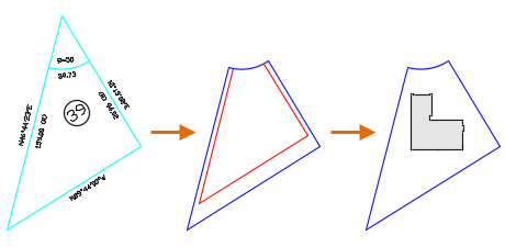
In the example below, you can use the setback lines as a reference to help you locate the foundation of the residence on the lot.
Manage with Layers
Keep your reference geometry on dedicated layers. If you choose layer names using a numeric prefix such as 00, 01, and so on, you can ensure that the layers will appear at the top of the layer list. You can then turn these layers on and off easily without having to scroll through the list of layers. You can also choose to assign reference layers a high transparency value or vibrant color, distinguishing reference geometry from other objects while managing the visual complexity of your drawing.