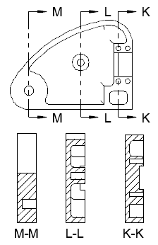
A model documentation cross section view is generated by slicing the entire length of the object being sectioned.
Note: Model documentation is available only on 64-bit systems.
- Click a layout tab to switch to paper space.
Note: The Layout ribbon tab displays automatically when a layout is active.
- Click
 .
.
- Click the view you want to use as the parent view. The start direction arrow appears at the cursor.
- Click in the drawing area to indicate the start point of the section line. The end direction arrow appears at the cursor.
- Click in the drawing area to indicate the end point of the section line. A preview of the section view appears at the cursor.
- Move the preview to the desired location and click to place the view.
Tip: The preview is constrained to move in a direction perpendicular to the section line. To relax the constraint, tap SHIFT. To restore the constraint, tap SHIFT again.
- Click
.
Find
Note: If you want to include geometry beyond the cutting plane, select Distance and specify the depth to which you want include details.
- Click
.