Selecting a 2D polyline provides specialized PEDIT options.
You can select a single arc or line segment, also called a subobject, within a polyline by pressing the Ctrl key when you click over it (not available in AutoCAD LT).
If the polyline you select is a closed polyline, Open replaces the Close option in the prompt. You can edit a 2D polyline if its normal is parallel to and in the same direction as the Z axis of the current UCS.
The following prompts are displayed.
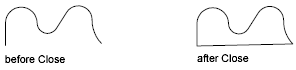
Close
Creates the closing segment of the polyline, connecting the last segment with the first. The polyline is considered open unless you close it using the Close option.
Open
Removes the closing segment of the polyline. The polyline is considered closed unless you open it using the Open option.
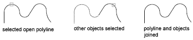
Join
Adds lines, arcs, or polylines to the end of an open polyline and removes the curve fitting from a curve-fit polyline. For objects to join the polyline, their endpoints must touch unless you use the Multiple option at the first PEDIT prompt. In this case, you can join polylines that do not touch if the fuzz distance is set to a value large enough to include the endpoints.
Jointype
Sets the method of joining selected polylines.
- Extend
-
Joins the selected polylines by extending or trimming the segments to the nearest endpoints.
- Add
-
Joins the selected polylines by adding a straight segment between the nearest endpoints.
- Both
-
Joins the selected polylines by extending or trimming if possible. Otherwise joins the selected polylines by adding a straight segment between the nearest endpoints.
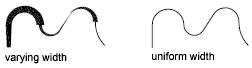
Width
Specifies a new uniform width for the entire polyline.
You can use the Width option of the Edit Vertex option to change the starting and ending widths of a segment.
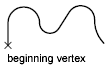
Edit Vertex
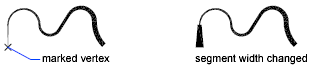
Marks the first vertex of the polyline by drawing an X on the screen. If you have specified a tangent direction for this vertex, an arrow is also drawn in that direction.
Next
Moves the X marker to the next vertex. The marker does not wrap around from the end to the start of the polyline even if the polyline is closed.
Previous
Moves the X marker to the previous vertex. The marker does not wrap around from the start to the end of the polyline even if the polyline is closed.
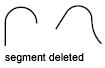
Break
Saves the location of the marked vertex while you move the X marker to any other vertex.
If one of the specified vertices is at an end of the polyline, the result is one truncated polyline. If both specified vertices are at endpoints of the polyline, or if just one vertex is specified and it is at an endpoint, you cannot use Break.
- Next
- Previous
- Go
-
Deletes any segments and vertices between the two vertices you specify and returns to Edit Vertex mode.
- Exit
-
Exits Break and returns to Edit Vertex mode.
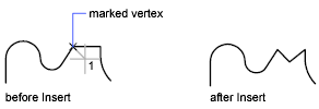
Insert
Adds a new vertex to the polyline after the marked vertex.
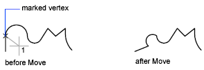
Move
Moves the marked vertex.
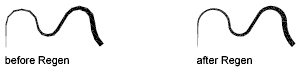
Regen
Regenerates the polyline.
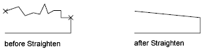
Straighten
Saves the location of the marked vertex while you move the X marker to any other vertex.
If you want to remove an arc segment that connects two straight segments of a polyline and then extend the straight segments until they intersect, use the FILLET command with a fillet radius of 0.
- Next
-
Moves the X marker to the next vertex.
- Previous
-
Moves the X marker to the previous vertex.
- Go
-
Deletes any segments and vertices between the two vertices you select, replaces them with single straight line segments, and returns to Edit Vertex mode. If you specify only one vertex by entering go without moving the X marker, the segment following that vertex is straightened if it is an arc.
- Exit
-
Exits Straighten and returns to Edit Vertex mode.
Tangent
Attaches a tangent direction to the marked vertex for use later in curve fitting.
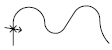
Width
Changes the starting and ending widths for the segment that immediately follows the marked vertex.
You must regenerate the polyline to display the new width.
Exit
Exits Edit Vertex mode.
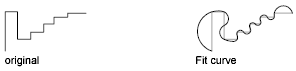
Fit
Creates an arc-fit polyline, a smooth curve consisting of arcs joining each pair of vertices. The curve passes through all vertices of the polyline and uses any tangent direction you specify.
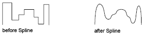
Spline
Uses the vertices of the selected polyline as the control points, or frame, of a curve approximating a B-spline. This curve, called a spline-fit polyline, passes through the first and last control points unless the original polyline was closed. The curve is pulled toward the other points but does not necessarily pass through them. The more control points you specify in a particular part of the frame, the more pull they exert on the curve. Quadratic and cubic spline-fit polylines can be generated.
Spline-fit polylines are very different from the curves produced by the Fit option. Fit constructs pairs of arcs that pass through every control point. Both of these curves are different from true B-splines produced with the SPLINE command.
If the original polyline included arc segments, they are straightened when the spline's frame is formed. If the frame has width, the resulting spline tapers smoothly from the width of the first vertex to the width of the last vertex. All intermediate width information is ignored. Once spline-fit, the frame, if displayed, is shown with zero width and CONTINUOUS linetype. Tangent specifications on control point vertices have no effect on spline-fitting.
When a spline-fit curve is fit to a polyline, the spline-fit curve's frame is stored so that it can be recalled by a subsequent decurving. You can turn a spline-fit curve back into its frame polyline by using the PEDIT Decurve option. This option works on fit curves in the same manner as it does on splines.
Most editing commands act the same when applied to spline-fit polylines or fit curves.
- MOVE, ERASE, COPY, MIRROR, ROTATE, and SCALE operate on both the spline curve and its frame, whether the frame is visible or not.
- EXTEND changes the frame by adding a new vertex where the initial or final line of the frame intersects the boundary geometry.
- BREAK and TRIM generate a polyline with only the fit spline, which is consistent with fit curves, where the curve fitting is permanent.
- EXPLODE deletes the frame and generates lines and arcs to approximate the spline-fit polyline.
- OFFSET generates a polyline with only the fit spline, which is consistent with its behavior with fit curves.
- DIVIDE, MEASURE, and the Object option of AREA and HATCH see only the fit spline, not the frame.
- STRETCH refits the spline to the stretched frame after a spline is stretched.
The Join option of PEDIT decurves the spline and discards the spline information of the original and any added polylines. Once the Join operation is complete, you can fit a new spline to the resulting polyline.
The Edit Vertex options of PEDIT have the following effect:
- The Next and Previous options move the X marker only to points on the frame of the spline, whether visible or not.
- The Break option discards the spline.
- The Insert, Move, Straighten, and Width options automatically refit the spline.
- The Tangent option has no effect on splines.
Object snap uses only the spline-fit curve itself, not the frame. If you want to snap to the frame control points, use PEDIT to recall the polyline frame first.
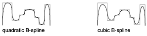
The SPLINETYPE system variable controls the type of spline curve approximated. Setting SPLINETYPE to 5 approximates a quadratic B-spline. Setting SPLINETYPE to 6 approximates a cubic B-spline.
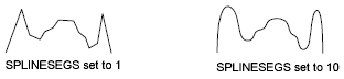
You can examine or change the fineness or coarseness of the spline approximation with the SPLINESEGS system variable. The default value is 8. If you set the value higher, a greater number of line segments are drawn and the approximation to the ideal spline becomes more precise. The generated spline occupies more space in the drawing file and takes longer to generate.
If you set SPLINESEGS to a negative value, the program generates segments using the absolute value of the setting and then applies a fit-type curve to those segments. Fit-type curves use arcs as the approximating segments. Using arcs yields a smoother generated curve when few segments are specified, but the curve can take longer to generate.
To change the number of segments used to fit an existing spline, change SPLINESEGS and respline the curve. You do not have to decurve it first.
Decurve
Removes extra vertices inserted by a fit or spline curve and straightens all segments of the polyline. Retains tangent information assigned to the polyline vertices for use in subsequent fit curve requests. If you edit a spline-fit polyline with a command such as BREAK or TRIM, you cannot use the Decurve option.
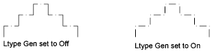
Ltype Gen
Generates the linetype in a continuous pattern through the vertices of the polyline. When turned off, this option generates the linetype starting and ending with a dash at each vertex. Ltype Gen does not apply to polylines with tapered segments.
Reverse
Reverses the order of vertices of the polyline. Use this option to reverse the direction of objects that use linetypes with included text. For example, depending on the direction in which a polyline was created, the text in the linetype might be displayed upside down.
Undo
Reverses operations as far back as the beginning of the PEDIT session.