Different edge types can be displayed using different colors and linetypes. You can also add special effects, such as jitter and line extensions.
In 3D solid or surface models, the current visual style sets the visibility and appearance of isolines, facet edges, silhouette edges, occluded edges, and intersection edges. Facet edges (the edges between planar faces representing a surface) are displayed only when the angle between the facets is smaller than the crease angle value you specify.
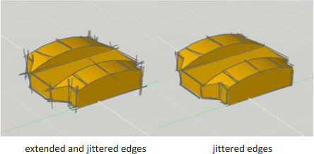
For example, edge modifiers such as line extension and jitter, produce the appearance of a model that is still in the conceptual phase. Jitter makes lines appear as though they were sketched with a pencil. Line extension produces another kind of hand-drawn effect.
Edges in the 2D Wireframe Visual Style
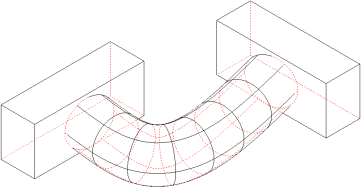
The 2D Wireframe visual style is optimized for 2D drawings, but it can also be used for 3D views. Several system variables control the display of 3D solid and surface models with this visual style. For example, the DISPSILH system variable controls the display of silhouette edges such as the apparent edges on a cylinder. Occluded lines are hidden lines that can be displayed with a distinctive linetype and color. Occluded lines can be assigned a distinctive linetype with the OBSCUREDLTYPE system variable and an occluded color with the OBSCUREDCOLOR system variable.