Geometric tolerances show acceptable deviations of form, profile, orientation, location, and runout of a feature.
You add geometric tolerances in feature control frames. These frames contain all the tolerance information for a single dimension. Geometric tolerances can be created with or without leader lines, depending on whether you create them with the TOLERANCE command, or with options in the LEADER and QLEADER commands.
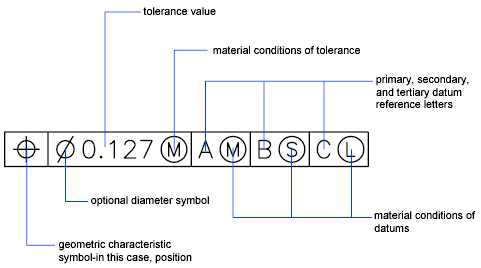
A feature control frame consists of two or more components. The first feature control frame contains a symbol that represents the geometric characteristic to which a tolerance is being applied, for example, location, profile, form, orientation, or runout. Form tolerances control straightness, flatness, circularity and cylindricity; profiles control line and surface. In the illustration, the characteristic is position.
You can use most editing commands and grips to change feature control frames, and you can snap to them using object snaps.
You can also create tolerances that use annotative scaling. For more information about creating and working with an annotative tolerances, see About Creating Annotative Dimensions and Tolerances, and About Scaling Annotations.