Special codes can be used to create additional geometric forms and specify certain actions.
The second character of the three-character string (the vector length specification) must be 0, or you can specify the special code number. For example, 008 and 8 are both valid specifications.
|
Specification byte codes |
||
|---|---|---|
|
Code |
Description |
|
|
000 |
End of shape definition |
Draw is activated at the start of each shape. When Draw mode is turned on (code 1), the vectors cause lines to be drawn. When Draw mode is turned off (code 2), the vectors move to a new location without drawing. |
|
001 |
Activate Draw mode (pen down) |
|
|
002 |
Deactivate Draw mode (pen up) |
|
|
003 |
Divide vector lengths by next byte |
The height specified with the SHAPE command is initially considered the length of a single orthogonal vector (direction 0, 4, 8, or C). Code 3 divides vector lengths by the next byte. Code 4 multiplies vector lengths by the next byte. Codes 3 and 4 are followed by a specification byte containing an integer scale factor (1 through 255). If you want the shape height to specify the size of the entire shape, and you use 10 vector lengths to draw it, you can use 3,10 to scale the height specification. The scale factor is cumulative within a shape; that is, multiplying by 2 and again by 6 results in a scale factor of 12. Usually, you should reverse the effect of your scale factors at the end of the shape, especially for subshapes and text font shapes. The program does not reset the scale factor for you. |
|
004 |
Multiply vector lengths by next byte |
|
|
005 |
Push current location onto stack |
You must pop everything you push. The position stack is only four locations deep. If the stack overflows because of too many pushes or too many missing pops, the following message is displayed when the shape is drawn. Position stack overflow in shape nnn Similarly, if you try to pop more locations than have been pushed onto the stack, the following message is displayed when the shape is drawn. Position stack underflow in shape nnn |
|
006 |
Pop current location from stack |
|
|
007 |
Draw subshape number given by next byte |
For a non-Unicode font the specification byte following code 7 is a shape number from 1 to 255. For a Unicode font, code 7 is followed by a Unicode shape number from 1 to 65535. Unicode shape numbers should be counted as two bytes. The shape with that number (in the same shape file) is drawn at this time. Draw mode is not reset for the new shape. When the subshape is complete, drawing the current shape resumes. |
|
008 |
X-Y displacement given by next two bytes |
Normal vector specification bytes draw only in the 16 predefined directions, and the longest length is 15. These restrictions help make shape definitions efficient but are sometimes limiting. Code 8 specifies the X-Y displacement given by the next two bytes. Code 8 must be followed by two specification bytes in the format: 8,X-displacement,Y-displacement The X-Y displacements can range from -128 to +127. A leading + is optional, and you can use parentheses to improve readability. The following example results in a vector that draws (or moves) 10 units to the left and three units up. 8,(-10,3) Following the two displacement specification bytes, the shape returns to Normal Vector mode. You can use code 9 to draw a sequence of nonstandard vectors. Code 9 specifies any number of X-Y displacement pairs. The code sequence is terminated by a (0,0) pair. The following example draws three nonstandard vectors and returns to Normal Vector mode. 9,(3,1),(3,2),(2,-3),(0,0) You must terminate the sequence of X-Y displacement pairs with a (0,0) pair in order for the program to recognize any Normal Vectors or special codes that follow. |
|
009 |
Multiple X-Y displacements, terminated (0,0) |
|
|
00A |
Octant arc defined by next two bytes |
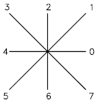
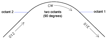
This is called an octant arc because it spans one or more 45-degree octants, starting and ending on an octant boundary. Octants are numbered counterclockwise from the 3 o'clock position, as shown in the following illustration.  The arc specification is 10,radius,(-)0SC The radius can be any value from 1 through 255. The second specification byte indicates the direction of the arc (counterclockwise if positive, and clockwise if negative), its starting octant ( s , a value from 0 through 7), and the number of octants it spans ( c , a value from 0 through 7, in which 0 equals eight octants, or a full circle). You can use parentheses to improve readability. For example, consider the following fragment of a shape definition: ...012,10,(1,-032),01E,... This code draws a one-unit vector up and to the right, a clockwise arc from octant 3 (with a radius of one unit for two octants), and then a one-unit vector down and to the right, as shown in the following illustration.  |
|
00B |
Fractional arc defined by next five bytes |
The definition uses five specification bytes. 11,start_offset,end_offset,high_radius,radius,(-)0SC The start_offset and end_offset represent how far from an octant boundary the arc begins or ends. The high_radius represents the most significant eight bits of the radius; the high radius will be 0 unless the radius is greater than 255 units. Multiply the high_radius value by 256 and add that value to the radius value to generate an arc radius greater than 255. The radius and ending specification byte are the same as for the octant arc specification (code 00A, described previously). You determine the startoffset by calculating the difference in degrees between the starting octant's boundary (a multiple of 45 degrees) and the start of the arc. Then, you multiply this difference by 256 and divide by 45. If the arc starts on an octant boundary, its start offset is 0. The end offset is calculated in a similar fashion, but you use the number of degrees from the last octant boundary crossed to the end of the arc. If the arc ends on an octant boundary, its end offset is 0. For example, a fractional arc from 55 degrees to 95 degrees with a 3 unit radius would be coded as follows: 11,(56,28,0,3,012) Here is the explanation: start_offset = 56 because ((55 - 45) * 256 / 45) = 56 end_offset = 28 because ((95 - 90) * 256 / 45) = 28 high_radius = 0 because (radius < 255) radius = 3 starting octant = 1 because arc starts in the 45 degree octant ending octant = 2 because arc ends in the 90 degree octant |
|
00C |
Arc defined by X-Y displacement and bulge |
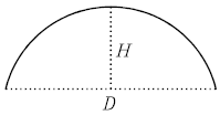
They are similar to codes 8 and 9 in that you can use them to specify X-Y displacements. However, codes 00C and 00D draw arcs by applying a bulge factor to the displacement vector. Code 00C draws one arc segment, while code 00D draws multiple arc segments (polyarcs) until it is terminated by a (0,0) displacement. Code 00C must be followed by three bytes describing the arc: 0C,X-displacement,Y-displacement,Bulge Both the X and Y displacement and the bulge, which specifies the curvature of the arc, can range from -127 to +127. If the line segment specified by the displacement has length D, and the perpendicular distance from the midpoint of that segment has height H, the magnitude of the bulge is ((2* H / D) * 127). The sign is negative if the arc from the current location to the new location is clockwise.  A semicircle has bulge 127 (or -127) and is the greatest arc that can be represented as a single-arc segment using these codes (use two consecutive arc segments for larger arcs). A bulge specification of 0 is valid and represents a straight-line segment. However, using code 8 for a straight-line segment saves a byte in the shape description. The polyarc code (00D, or 13) is followed by 0 or by more arc segment triples, and is terminated by a (0,0) displacement. Note that no bulge is specified after the final displacement. For example, the letter S might be defined by the following sequence: 13,(0,5,127),(0,5,-127),(0,0) Zero bulge segments are useful within polyarcs to represent straight segments; they are more efficient than terminating the polyarc, inserting one straight segment, and then starting another polyarc. The number -128 cannot be used in arc segment and polyarc definitions. |
|
00D |
Multiple bulge-specified arcs |
|
|
00E |
Process next command only if vertical text |
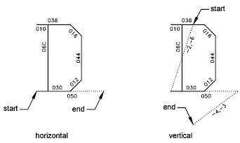
When this special code is encountered in a character definition, the next code is either processed or skipped, depending on orientation. If the orientation is vertical, the next code is processed; if it is horizontal, the next code is skipped. In horizontal text, the start point for each character is the left end of the baseline. In vertical text, the start point is assumed to be the top center of the character. At the end of each character, a pen-up segment is normally drawn to position to the next character's start point. For horizontal text, it is to the right; for vertical text, it is downward. The special 00E (14) code is used primarily to adjust for differences in start points and endpoints, permitting the same character shape definition to be used both horizontally and vertically. For instance, the following definition of an uppercase D could be used in either horizontal or vertical text. *68,22,ucd 2,14,8,(-2, 6),1,030,012,044,016,038,2,010,1,06C,2,050, 14,8,(-4,-3),0  |