Have you ever tried entering a coordinate value only to get an unexpected result? Chances are, you have worked with coordinates as they are one of the fundamental pieces of information required by most commands in AutoCAD to create or modify objects. This article looks at entering coordinates and the impact Dynamic Input has on coordinate entry.
AutoCAD accepts the following coordinate value types:
- Absolute Cartesian – Precise location by entering a two (XY) or three (XYZ) coordinate value.
- Relative Cartesian – Location from a previous coordinate value using a two (XY) or three (XYZ) coordinate value.
- Polar – Location from a previous coordinate value based on a distance and an angle from the X axis to define a point.
How you enter those coordinate value types depends on two factors:
- Is Dynamic Input enabled?
- Are you being prompted to specify a first or subsequent point?
What’s Dynamic Input?
Before we talk about coordinate entry, we need to talk about Dynamic Input. Dynamic Input is a feature that allows you to enter coordinate, length, and angular values near the crosshairs along with text strings and command options.
When a command is started, and if Dynamic Input is enabled, the main prompt of the current command is repeated near the crosshairs along with several tooltips that accept input. For example, if you start the CIRCLE command, AutoCAD prompts for a coordinate value to define the center point of the circle.
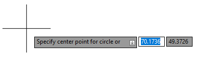
Here are the steps you would follow to draw a circle with a center point of 3.5,5 and a radius of 1.25 using Dynamic Input:
| Steps | Results |
|---|---|
|
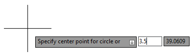
AutoCAD prompts you for a coordinate value that represents the center point of the circle. Three tooltips are displayed with focus set to the second tooltip which represents the X coordinate value. |
|
The focus moves to the third tooltip which represents the Y coordinate value. |
|
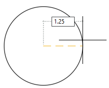
The absolute coordinate value of 3.5,5 is used as the center point of the circle and the next prompt of the CIRCLE command is displayed in the Dynamic Input tooltip. Note: Instead of pressing Enter to specify a 2D coordinate value, you could have typed a comma and then entered a number for the
Z coordinate value.
|
|
A circle with a center point of 3.5,5 is drawn with a radius of 1.25. |

In the previous example, you could have done one of three things at the Specify radius of circle prompt:
- Specified a radius value in the form of a length. Type in the radius value to use and press Enter, which is what was explained.
- Specified a coordinate value from the center point of the circle to define the radius value. Type an X coordinate value followed by a comma. Then type a Y coordinate value and press Enter for a 2D coordinate value. Or type a comma again to provide a Z coordinate value for a 3D coordinate value and then press Enter.
- Switched to the Diameter input option. Press the Down Arrow key twice and press Enter. When prompted for a diameter value, enter a length or coordinate value as described in the previous two bullets.
When you were prompted for the radius of the circle, did you notice the icon with the downward arrow at the end of the tooltip?
This icon indicates there are other options available. When prompted for a radius, clicking the downward arrow or pressing the Down Arrow key, displays a menu with the Diameter option. Choosing Diameter allows you to specify a diameter for the circle instead of a radius value. When the menu is displayed, you can move through the available options by pressing the Down and Up Arrow keys or the pointing device.

Turning Dynamic Input On or Off
Dynamic Input is turned on by default and can be toggled on or off by clicking the Dynamic Input icon ( ) on the status bar or pressing F12. When on, the Dynamic Input icon should appear with a blue background ( Find).
Enter Coordinate Values with Dynamic Input
When using Dynamic Input, the first coordinate value you specify for a command is assumed to be absolute unless specified otherwise.
The following explains how to enter coordinate values in Dynamic Input tooltips:
- Absolute – Type a coordinate value in the format of #X,Y or #X,Y,Z
Examples: #3.5,5 or #3.5,5,-1
Note: The # is only needed, if you want to specify an absolute coordinate value when prompted for a next point. - Relative – Type @ and then a coordinate value in the format of
X,Y or
X,Y,Z
Examples: @3.5,5 or @3.5,5,-1
- Polar – Type a distance, followed by a less than symbol (<), and then the angular value to define the direction from the
X axis
Examples: 3.5<45 or -1.25<60
- Polar Relative – Type @ and then type a polar coordinate value
Examples: @3.5<45 or @-1.25<60
In this exercise, you draw a rectangle with line segments by entering absolute, relative, and polar coordinates using Dynamic Input.
| Steps | Results |
|---|---|
|
The LINE command is started. |
|
This defines the first point of the line at an absolute coordinate of 22.5,30 on the current working plane. |
|
This defines a point 22 units along the X axis and 0 units along the Y axis relative to the first point, resulting in a horizontal line that is 22 units long. Note: If a horizontal line isn’t drawn, enter
u to undo the previous line segment and enter
@22,0. See the Control Dynamic Input section for information.
|
|
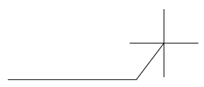
This defines a point 6 units away from the previous point at an angle of 90 degrees from the X axis, resulting in a vertical line that is 6 units long. Note: If you had typed -6, the vertical line would have been drawn downward at an angle of 90 degrees from the
X axis.
|
|
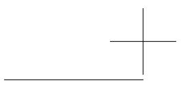
This defines an absolute coordinate of 22.5,36 which is 6 units above the original point on the Y axis, resulting in a horizontal line that is 22 units long. |
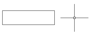
|
The resulting rectangle should start at 22.5,30 and have a length of 22 units and a width of 6 units. |


Tips for Entering Coordinates
- While it’s not required to use a # (pound sign) to define an absolute coordinate value when prompted for the first point, it is a good habit to include a # so you don’t have to worry about the rules of when it is and isn’t needed.
- Instead of pressing comma to move to the next Dynamic Input tooltip, you can press Tab if you are entering either an absolute or relative coordinate value that isn’t a polar coordinate value.
- If you frequently work in 3D, you can display the input tooltip for the Z coordinate value by checking Show Z Field for Pointer Input on the 3D Modeling tab of the Options dialog box (OPTIONS command). This setting isn't available in AutoCAD LT.
Control Dynamic Input
By default, the coordinate entry for the second or next point is relative to the previous point specified and the Dynamic Input tooltips are only displayed when a command is active. You can change the settings of Dynamic Input to control:
- When Dynamic Input tooltips are displayed
- The coordinate entry format for the second or next point
- The overall appearance of the tooltips
The settings for Dynamic Input can be found on the Dynamic Input tab of the Drafting Settings dialog box (DSETTINGS command). You can display the Dynamic Input tab of the Drafting Settings dialog box, by doing one of the following:
- Right-click over the Dynamic Input button on the status bar and choose Dynamic Input Settings.
- At the Command prompt, enter dsettings. In the Drafting Settings dialog box, click the Dynamic Input tab.
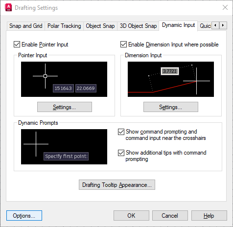
The following provides an overview of the settings on the Dynamic Input tab of the Drafting Settings dialog box:
- Pointer Input - Controls the behavior of coordinate entry for the second or next point, and when the coordinates are to be shown.
- Dimension Input - Controls the behavior of dimension input tooltips used to request length, angular, and radius values.
- Dynamic Prompts - Controls the display of prompt and input tooltips near the crosshairs.
- Drafting Tooltip Appearance - Controls the appearance of the input tooltips; color, size, and transparency.
The settings under Pointer Input impact how you enter coordinate values while Dynamic Input is active. Click Settings to open the Pointer Input Settings dialog box.
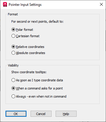
In the Pointer Input Settings dialog box, you can control the format in which the second or next point needs to be entered while using Dynamic Input. The default format settings are: Polar Format and Relative Coordinates. Setting it to Relative coordinates saves you from having to enter the @ symbol before entering the second or next coordinate value for a command.
The Visibility setting controls when the Dynamic Input tooltips are displayed. By default, they are only displayed when a command is active.
Tips for the Display of Dynamic Input Tooltips
- If you set the Visibility setting to always display Dynamic Input tooltips, the current position of the crosshairs will be displayed in the Dynamic Input tooltips when a command isn’t active.
- Do you find the text to be a bit too small in the Dynamic Tooltips? If so, you can increase the size of the text by opening the Drafting Settings dialog box (DSETTINGS command), clicking on the Dynamic Input tab, and then clicking Drafting Tooltip Appearance. In the Tooltip Appearance dialog box, slide the Size slider to the right to increase the tooltip’s text size. Click OK twice to apply the changes.
| Command | Description |
|---|---|
| DSETTINGS | Sets grid and snap, polar and object snap tracking, object snap modes, Dynamic Input, and Quick Properties. |
| System Variable | Description | Default Value | Saved In |
|---|---|---|---|
| DYNDIGRIP | Controls which dynamic dimensions are displayed during grip stretch editing. | 31 | Registry |
| DYNDIVIS | Controls how many dynamic dimensions are displayed during grip stretch editing. | 1 | Registry |
| DYNINFOTIPS | Controls whether tips are displayed for using Shift and Ctrl when editing with grips. | 1 | Registry |
| DYNMODE | Turns Dynamic Input features on and off. | 3 | Registry |
| DYNPICOORDS | Controls whether pointer input uses relative or absolute format for coordinates. | 0 | Registry |
| DYNPIFORMAT | Controls whether pointer input uses polar or Cartesian format for coordinates. | 0 | Registry |
| DYNPIVIS | Controls when pointer input is displayed. | 1 | Registry |
| DYNPROMPT | Controls display of prompts in Dynamic Input tooltips. | 1 | Registry |
| DYNTOOLTIPS | Controls which tooltips are affected by tooltip appearance settings. | 1 | Registry |
Coordinate values are required to accurately position objects within a design. Hopefully, the next time you need to enter a coordinate value, you will be able to avoid past problems you might have had based on what you learned in this article.