Have you ever wondered what that thing is in the lower left corner of the drawing area and curious about what it does? Or maybe you know it's the UCS (User Coordinate System) icon but because you don't create 3D models, you don't think it's useful for 2D work. Let's spend some time on what the UCS is and how you might use it in 2D drafting.
The UCS establishes the origin and orientation of a movable Cartesian coordinate system. By moving and changing the orientation of the UCS, you can relocate 0,0 of your drawing.
As you move the origin of the UCS, the drawing grid also moves and orients itself to the new origin. The main axis lines of the grid show the positive directions of the X (red line) and Y (green line) axis.
Here's an example of a way to use the UCS in 2D drafting that can improve your productivity.
Align the UCS with the angled walls
First, if the UCS icon is not displayed, turn it on by clicking the View tab and toggle the UCS icon control.
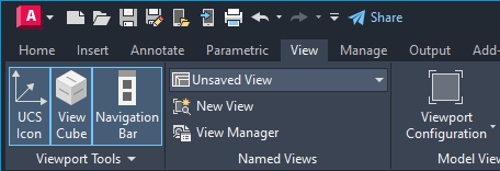
You should now see the UCS icon in the drawing area.
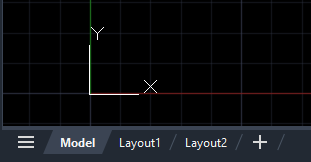
Let's also make sure the grid is turned on by clicking the grid icon on the status bar. This toggles the grid on or off.

Now that the UCS icon is displayed it can be moved and rotated in the drawing. Moving and aligning the UCS icon is useful when you have an angled area of a drawing that you want to work on without having to continuously input the angle for each new line.
In this example, I'll align the UCS with the angled walls in this floor plan.
- Click the UCS icon.
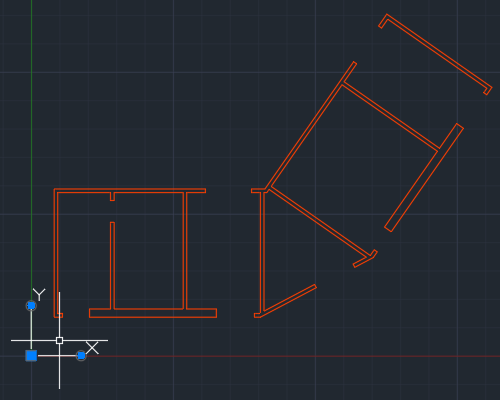
- Click the move grip. The UCS icon should now be moving with the cursor.
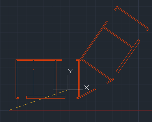
- Drag it to the endpoint of the wall and use an Endpoint object snap to ensure proper placement.
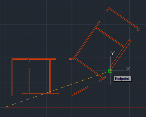
- With the UCS icon repositioned, click the round grip at the end of the x-axis and snap to the Endpoint of the wall.
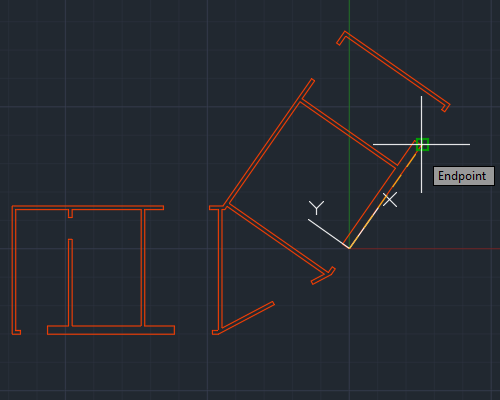
Along the x-axis of the UCS, you'll also notice that the cursor and grid lines are rotated to be parallel with the wall.
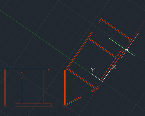
Now, you can easily align all new lines to the rotated walls of the building.
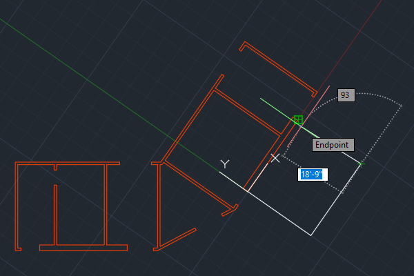
Resetting the UCS to World
With the UCS aligned to these walls, you might be thinking how do I get it back to the way it was. Well, you can select the UCS icon, hover over the move grip, and choose World.
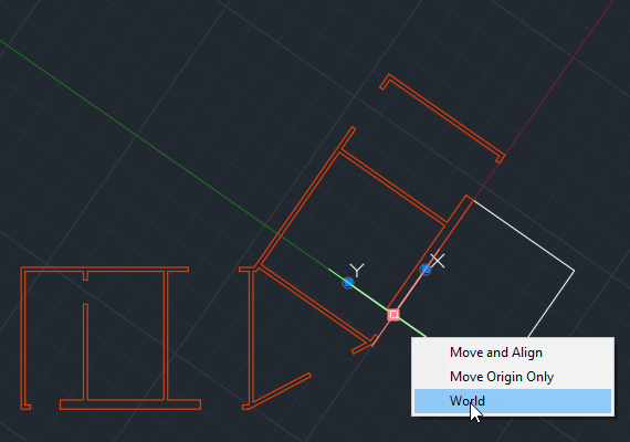
This sets the UCS back to the World Coordinate System (WCS).
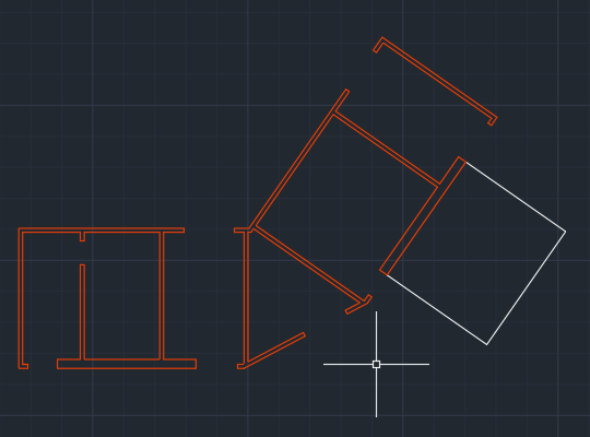
Customizing the appearance of the UCS icon
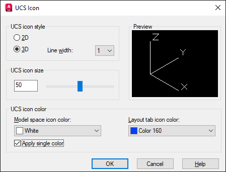
In addition to moving and orienting the UCS icon, the appearance can also be customized. Let's say you want to make the UCS icon larger or a different color. You can do this by right clicking on the UCS icon. From the shortcut menu, choose .
Here you can set the icon style, size, color and other settings.
Control the Behavior of the UCS icon
You can control the behavior of the UCS icon by setting certain commands and system variables. Here are the commands and system variables related to the UCS and UCS icon.
| Commands | Description |
|---|---|
| UCSICON | Controls the visibility, placement, appearance, and selectability of the UCS icon. |
| UCS | Sets the origin and orientation of the current user coordinate system (UCS). |
| System Variable | Description | Default Value | Saved In |
|---|---|---|---|
| UCS2DDISPLAYSETTING | Displays the UCS icon when the 2D Wireframe visual style is current. | 1 | Registry |
| UCS3DPARADISPLAYSETTING | Displays the UCS icon when perspective view is off and a 3D visual style is current. | 1 | Registry |
| UCS3DPERPDISPLAYSETTING | Displays the UCS icon when perspective view is on and a 3D visual style is current. | 1 | Registry |
| UCSICON | Controls the visibility and placement of the UCS icon. | 3 | Drawing |
See the Help topic Commands for the User Coordinate System (UCS) for a more comprehensive list of UCS related commands and system variables. Hover over the name to see a brief description.