Wouldn't it be great to simplify your workflows and repetitive tasks through automation? I know, what you might be thinking… "Sounds great, but I'm not a programmer."
You don't need to be a programmer to automate repetitive tasks with action macros. You just need to know how to use AutoCAD, more specifically, how to use commands and system variables. As you use commands, certain commands are often used frequently together and in the same order, this is known as a command sequence. Command sequences make the best candidates to be automated.
Action macros are a recorded sequence of commands, options, and values that can be played back in any drawing. You might create an action macro that:
- Sets a layer and style current before adding a dimension or annotation.
- Changes the layer and scale of selected objects.
- Cleans up a drawing by moving certain types of objects to a specific layer, setting all objects to ByLayer, and purging unused named objects, such as layers and blocks.
- Inserts a title block with a specific location and scale, adds several floating viewports at default locations, and creates labels below each viewport.
Which Commands and Actions Can Be Recorded?
Most commands can be recorded, such as the LINE command to draw lines, CHPROP command to change the properties of an object, and the LAYER command used to manage layers in a drawing.
The commands that can't be recorded are related to:
- Creating, opening, and recovering drawing files
- Using the Action Recorder and Visual Basic for Applications features
- Pressing and pulling 3D objects
- Editing the contents of table cells
You can find a list of AutoCAD commands that can't be recorded in the Customization Guide in the topic About Recording Action Macros.
An action is the smallest interaction in AutoCAD that can be recorded, these general interactions can be recorded:
- Start of a command
- Specification of values: coordinate point, object selection, and string/numeric values
- Changes to the current drawing view
You can find a list of actions and user interfaces that can be recorded in the Customization Guide in the topic About Recording User Interface Elements.
Record an Action Macro
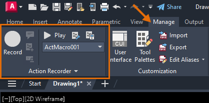
Action macros are recorded using the Action Recorder located on the Manage tab of the ribbon. Think of the Action Recorder as AutoCAD's version of an audio recorder or digital video recorder (DVR).
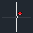
When recording starts, a red circle appears adjacent to the crosshairs letting you know the Action Recorder is actively listening for actions.
Let's look at recording an action macro that could be used to setup a drawing. This action macro will do the following:
- Set an existing layer current
- Set the midpoint, endpoint, center, and intersection running object snaps current
- Create a linear dimension
- Restore the previous layer
- Create a new drawing.
- Add the layer "Dimensions" and assign the layer the color 3.
- On the ribbon, click Manage tab > Action Recorder panel > Record. Find
- At the Command prompt, enter
CLAYER and then enter a name of
Dimensions.
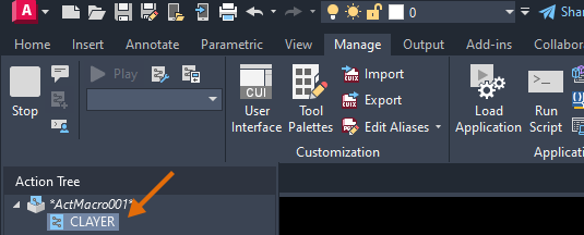
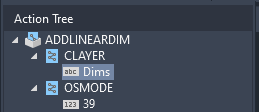
Notice the CLAYER system variable is recorded and shown in the Action Tree.
- At the Command prompt, enter
OSMODE and then enter a value of
39.
The value 39 sets the midpoint, endpoint, center, and intersection running object snaps current.
- At the Command prompt, enter DIMLINEAR.
- At the Specify first extension line origin prompt, specify a point in the drawing.
- At the
Specify second extension line origin prompt, move the cursor to the right and specify a point.

- At the
Specify dimension line location prompt, move the cursor up and specify a point.

- At the Command prompt, enter
LAYERP.
The previous layer is restored.
- On the ribbon, click Manage tab > Action Recorder panel > Stop. Find
- In the Action Macro dialog box, Action Macro Command Name text box, enter
ADDLINEARDIM.
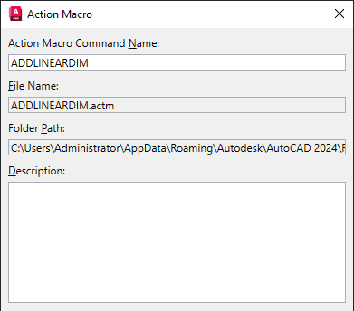
- Optionally, enter a description for the macro in the Description text box.
- Click OK to save the action macro to a file with the ACTM extension.
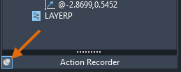
If you expand the Action Record panel, the completed macro should look like the following image.

- Click the pin button on the Action Recorder panel to allow the panel to collapse.
Playback an Action Macro
After an action macro has been recorded, it can be played back using one of the following methods:
- At the Command prompt, enter the name of an action macro.
- In the drawing window, right-click and choose Action Macro > Play and then an action macro.
- On the ribbon, click Manage tab > Action Recorder panel and choose an action macro from the drop-down list. Then click Play.
The following steps explain how to playback the ADDLINEARDIM action macro that was recorded earlier:
- Create a new drawing and turn off Object Snap (F3).
- Add the layer "Dimensions" to the drawing, but don't set it current.
Note: If the layer doesn't exist, you will get an error when playing back the macro. To avoid this, you could use the -LAYER command with the Make option to create the layer, if it doesn't exist in the drawing already, instead of the CLAYER system variable to set a layer current.
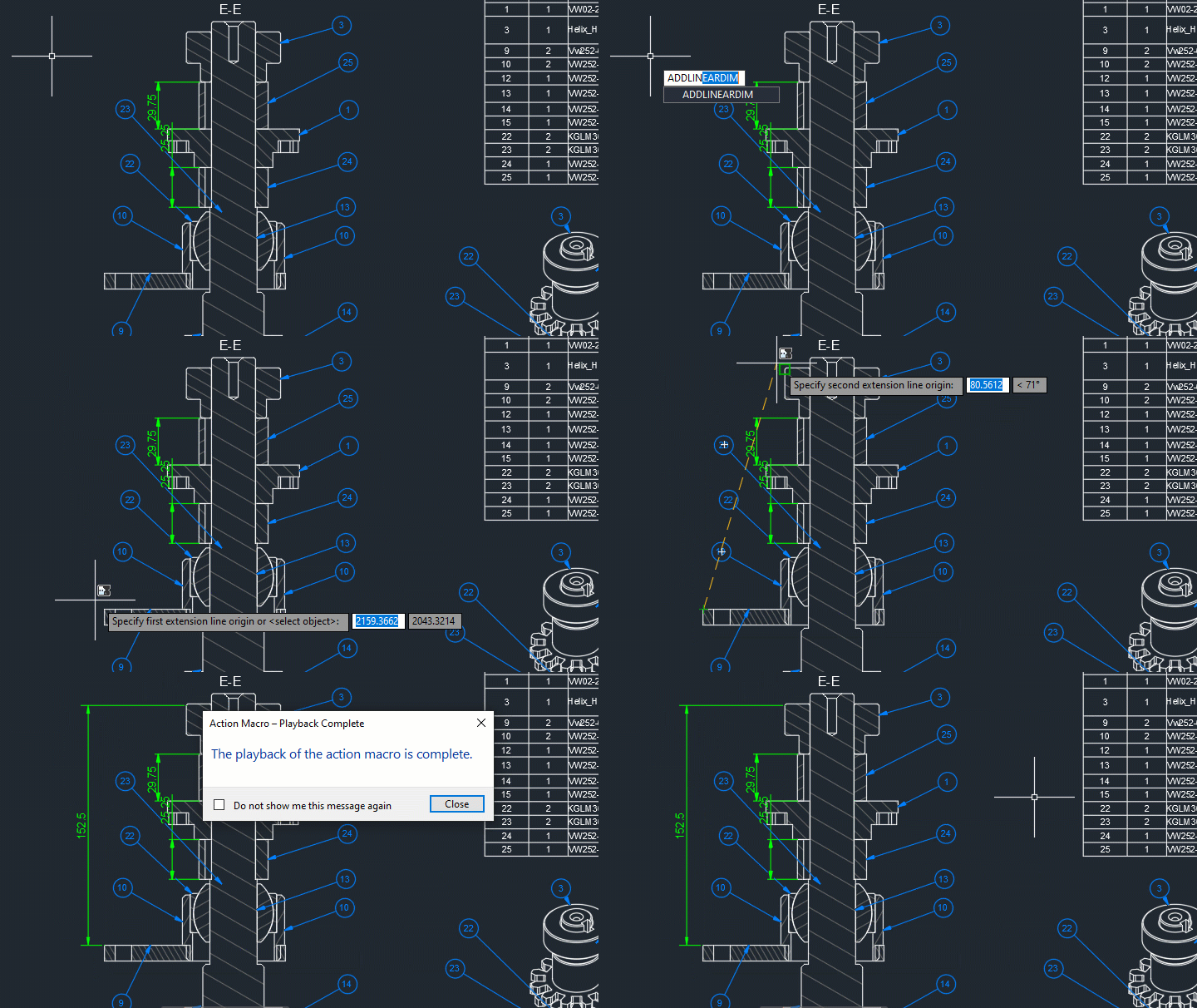
- At the Command prompt, enter ADDLINEARDIM.
- In the Action Macro – Playback Complete message box, click Close.
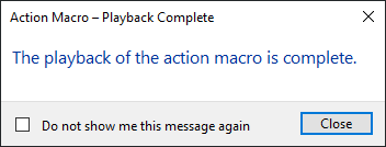
Object snap should now be enabled with a linear dimension drawn on the Dimensions layer.

Edit and Request Input an Action Macro
After an action macro has been saved to an ACTM file, you can make the following types of changes to it:
- Edit recorded values: color, scale factor, and coordinates
- Remove commands and view changes
- Add prompts for user input during playback: enter a value, specify a point, or select objects
- Indicate pre-selected objects are to be used by the action macro during played back
- Change coordinate values between absolute or relative to the previous point
- Insert a user message to provide the user with information about the action macro
- Define the base point from which all points in the action macro should be relative to
You make changes to an action macro by making sure it is current in the Action Macro drop-down list and expanding the Action Recorder panel to see the Action Tree.
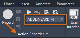

With the Action Tree expanded:
- Select and then double-click a recorded value to assign it a new value
- Right-click a recorded value and choose Pause for User Input to allow the user to provide a value during playback
- Right-click a recorded command or a view change node and choose Delete to remove it
Note: Command options and values can't be removed.
The following steps explain how to change the name of the layer to Dims and prompt the user to provide the locations of the extension and dimensions lines during playback:
- On the ribbon, click Manage tab > Action Recorder panel. From the drop-down list, choose ADDLINEARDIM.

- Click the title bar of the Action Recorder panel to expand it and display the Action Tree.
Note: If the Action Recorder panel doesn't expand, try setting the ACTUI system variable to a value of 7 and playback the action macro. If the panel still doesn't expand, close and restart the product.
- In the lower-left corner of the expanded panel, click the pin button to keep the Action Recorder panel from collapsing.

- With the Action Recorder panel expanded and the Action Tree visible, select and then double-click the recorded String value of
Dimensions under the
CLAYER system variable and enter a new value of
Dims.
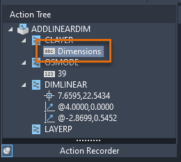
Now when the action macro is played back, the Dims layer will be set current instead of Dimensions.
- Under the DIMLINEAR command node, right-click over each coordinate value and choose Pause for User Input.
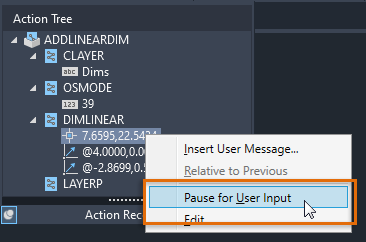
Each coordinate value should now appear with italic text and have a Silhouette badge overlay. Now during playback, you will be prompted to specify a location for the first and second extension lines along with the dimension line.

- Create a new drawing and then add then a layer named Dims.
- Playback the action macro.
- Specify three points to define the dimension.
The dimension is placed on the Dims layer this time.
Before removing a <View Change> node, create a copy of your action macro with the Action Macro Manager dialog box (ACTMANAGER command) and then remove the <View Change> node from the copy of the action macro. Once the action macro has been copied, followed these steps:
- If the action macro to edit isn't selected, choose it from the Action Macro drop-down list.
- Expand the Action Recorder panel if it isn't already and scroll to the <View Change> node.
- Right-click over the <View Change> node and choose Delete.
- In the Action Macro – Confirm Deletion of Action Node, click Delete.

- Create a new drawing and playback the action macro again.
This time, the drawing's view shouldn't be changed unless desired.
Manage and Share an Action Macro (ACTM) Files
Action macros are stored in ACTM files. ACTM files can be stored in a shared location, allowing for multiple users to use them. There are two types of folders the Action Recorder and AutoCAD look in for ACTM files:
- Actions Recording File Location – New action macros are recorded to and can be edited from this location.
- Additional Actions Reading File Locations – AutoCAD loads action macro files found in these locations as read-only, restricting edits from being made to them.
These folder locations are defined under the Action Recorder Settings node on the Files tab of the Options dialog box. The following steps explain how to add an additional location for ACTM files:
- In the drawing window, right-click and choose Options.

- In the Options dialog box, Files tab, expand the Action Recorder Settings node.

- Select the Additional Actions Reading File Locations node.
- Click Add and then click Browse.
- In the Browse for Folder dialog box, choose the folder that contains any additional ACTM files to load into AutoCAD, and click Open (or OK).
- Click OK to save the changes made in the Options dialog box.
Summary
Action macros allow you to instruct AutoCAD to execute multiple commands with consistent results which help to simplify workflows, reduce repetitive tasks, and enforce CAD standards though automation. Automation can free up time and allow you to focus on your designs rather than the design tool.
Additional Things to Know When Recording Actions
- While commands that display dialog boxes can be recorded, the actions performed in a dialog box are not recorded. It is best to use a command's alternative version which displays prompts in the command line window or a Dynamic Input tooltip. This helps ensure the consistent playback of an action macro. As an example, you would use the -PLOT or -STYLE command instead of the PLOT or STYLE command.
- Actions performed with the Layer Properties Manager can result in the recording of extra uses of the -LAYER command. It is recommended to use the -LAYER command at the Command prompt to give you control over the actions recorded.
- Action macros can be used within command macros to automate certain workflows that might normally not be accessible to a command, such as editing dynamic block properties and accessing tools from a tool palette.
Action Macros Commands and System Variables
Here are some frequently used commands and system variables related to action macros.
| Command | Description |
|---|---|
| ACTBASEPOINT | Inserts a base point or base point prompt in an action macro. |
| ACTMANAGER | Manages action macro files. |
| ACTRECORD | Starts the recording an action macro. |
| ACTSTOP | Stops the Action Recorder and provides the option of saving the recorded actions to an action macro file. |
| ACTUSERINPUT | Pauses for user input in an action macro. |
| ACTUSERMESSAGE | Inserts a user message into an action macro. |
| System Variable | Description | Default Value | Saved In |
|---|---|---|---|
| ACTPATH | Specifies the additional paths to load action macros from for playback. | "" | Registry |
| ACTRECORDERSTATE | Specifies the current state of the Action Recorder. | 0 | Not-saved |
| ACTRECPATH | Specifies the path used to store new action macros. | "" | Registry |
| ACTUI | Controls the behavior of the Action Recorder panel when recording and playing back macros. | 6 | Registry |