In the Insert Blocks Quickly with Tool Palettes topic, we explained how to insert blocks using tool palettes. In this Have You Tried we’re going to show you that tool palettes go beyond just inserting blocks. In addition to quickly inserting blocks, creating tools on tool palettes provide significant increases in efficiency for other types of content, including:
- Hatches and fills
- Dimensions and leaders
- Tables
- Geometric objects
By creating tools from existing geometry, you can ensure CAD standards are applied consistently and reduce steps in existing workflows.
Discuss and Share with Others
Have You Tried articles can jumpstart new ways of working with AutoCAD, you can discuss and share ideas with others in the companion post on the AutoCAD forum.
Add a Tool Based on an Existing Hatch Object
The following steps explain how to create a hatch tool from an existing hatch object in a drawing:
- Open or create a drawing file that contains a hatch object.
- Click View tab > Palettes panel > Tool Palettes (or enter TOOLPALETTES at the Command prompt) to display the Tool Palettes window. Find
- Right-click one of the tabs on the Tool Palettes window and choose New Palette. Give the new palette a meaningful name, such as the name of a drafting discipline, client, or project.
- In the drawing area, select a hatch object.
- Press and hold the right mouse button, drag the hatch object onto the tool palette.
That’s all there is to it, you just created a tool based on the selected hatch object.
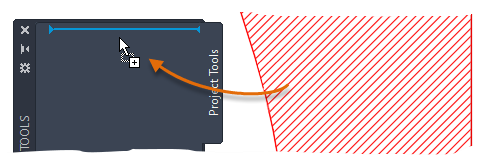
- On the Tool Palettes window, click the new hatch tool and pick a point (or drag and drop the hatch tool) within an enclosed area to apply a hatch pattern.
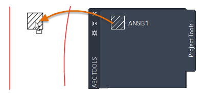
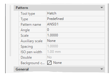
The new hatch object includes all the property settings from the original hatch.
Add and Customize a Tool Based on an Existing Dimension
A dimension tool can be created by dragging a dimension object onto a tool palette. When a new dimension tool is created, the tool contains a flyout button.
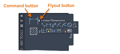
The following steps explain how to create and customize a dimension tool based on an existing dimension:
- Open or create a drawing that contains a dimension object.
Make sure the Tool Palettes window is displayed, and on the tab, you want to customize.
- In the drawing area, select a dimension object.
- Press and hold the right mouse button and drag the dimension object onto the tool palette.
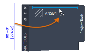
- Right-click the new dimension tool on the tool palette and choose Properties to edit its properties and behavior.
- In the Tool Properties dialog box, under the Command section, you can edit the properties that control the behavior of the dimension tool.
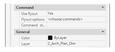
- Use Flyout – Enables the display of a flyout button for the tool.
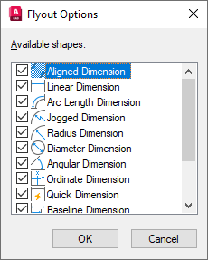
- Flyout Options – Controls which commands are displayed when the flyout menu is displayed.
- Command String – Includes the command macro to run when the tool is clicked. This option is available only when the Use Flyout option is turned off.
- Under the General section, edit the general properties to be applied to new dimension objects created with the tool.
- When you are done making changes, click OK.
- In the Tool Properties dialog box, under the Command section, you can edit the properties that control the behavior of the dimension tool.
- On the Tool Palettes window, click the main button of the new dimension tool or the flyout button and then one of the associated tools. Follow the prompts.
Add a Command Tool
You learned how tools can be created from existing drawing objects. Tools can also be created from your favorite commands. For example, the Rectangular Revision Cloud command can be added to a tool palette and customized to set a layer current when the tool is used. Using this technique, you can quickly create custom versions of your favorite tools.
The following steps explain how to add the Rectangular Revision Cloud command to a tool palette:
- With the Tool Palettes window displayed, right-click its title bar or in an empty area near a tool and choose Customize Commands.

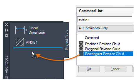
- In the Customize User Interface (CUI) Editor, under the Command List pane, click in the Search Command List text box and type
revision.
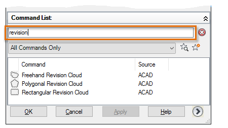
- In the Commands List, drag the Rectangular Revision Cloud command onto the tool palette.
- Close the CUI Editor.
- On the Tool Palettes window, right-click the Rectangular Revision Cloud tool and choose Properties.
- In the Tool Properties dialog box, under the General section, click the Layer property and choose the layer to be set current when you use the tool.
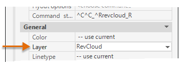
Note: The layer must already exist in the current drawing before it can be assigned to the tool. When the tool is used in a drawing that doesn’t contain the assigned layer, the layer is automatically created before it runs the command. - Click OK to apply the change.
- Click the Rectangular Revision Cloud tool and follow the prompts.