You've just received a 3D model for your review, and you would like to feel more comfortable changing views and controlling how the model displays. This topic covers the easiest ways to do the following:
- Specify standard 3D views
- Control the appearance of 3D models
- Rotate 3D views dynamically
- Switch between parallel and perspective projections
Create a Simple 3D Model
To start, create three rectangles using the RECTANG command and three circles like this:
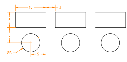
Three Viewport Controls
In the upper-left corner of every viewport, there are three controls:
[-] [Top] [2D Wireframe]
You can click each one of the three bracketed areas to change various settings and controls.
- The [-] menu includes options for displaying several viewports or controlling the display of view navigation tools.
- The [Top] menu includes a list of standard and custom views.
- The [2D Wireframe] menu includes a list of available visual styles.
Go ahead and click the [-] control, look at menu, and press Esc. Do the same for the [Top] and [2D Wireframe] controls. The titles will change to display the current setting.
- Click the control labeled [Top] and then choose SE Isometric from the menu.
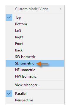
This operation displays an isometric view of the drawing.
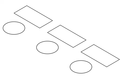
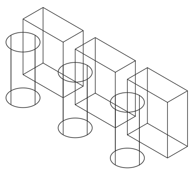
- Enter EXTRUDE at the Command prompt and select all six objects.
- Enter 12 as the extrusion distance.
Visual Styles
You've just created six 3D solids that are displayed using the 2D Wireframe visual style. Visual styles determine the display of edges, lighting, and shading in each viewport. Let's explore these visual styles.
- First change the colors of the 3D solids using the Properties palette or the ribbon control as shown.

- From the viewport controls, click [2D Wireframe] and choose Conceptual from the menu.

- From the same menu, choose each of the other visual styles to see what they look like and then return to the Conceptual visual style. Below are examples of the Conceptual, Hidden, and X-ray visual styles.
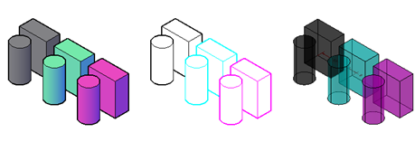
Comparing the 2D Wireframe with the Wireframe Visual Style
So what's the difference between the 2D Wireframe and the Wireframe visual styles?
- [2D Wireframe]
- This visual style is optimized for maximum speed in 2D drawings. However in 3D views, the 2D Wireframe visual style results in a REGEN operation every time you change the view orientation.
- [Wireframe]
- This visual style is optimized for 3D viewing and does not regenerate the view when you change the 3D view direction. Additionally, draw order settings and fills from 2D solid objects are not displayed. These differences can save you a significant amount of time when working in large 3D models.

Rotate 3D Views Dynamically
You can easily rotate the view of a model dynamically, which gives you the advantage of parallax to make a complex model easier to comprehend as compared to a static view.
- Press and hold down Shift and then press and hold down the mouse wheel.
- While keeping Shift and the mouse wheel pressed down, move the mouse around.
While in this mode, you can see both a dark-green ball (1) that indicates the target point about which your view rotates. Also, your cursor changes to a view rotate cursor (2). Your cursor location is important when you use the scroll wheel to zoom in and out.
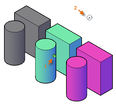
- Release the Shift and the mouse wheel to stop changing the view.
- To return to a standard view, click [Custom] from the viewport controls and choose SE Isometric again.
Control the Background Color
In some cases, you might want to change the background color of the 3D view. For example, you might want a white background for illustrating documents and presentations. To change the background color to white, follow these steps:
- Enter OPTIONS to display the Options dialog box and click the Display tab, Colors button.

The relevant contexts in the left column are 2D model space, 3D parallel projection, and 3D Perspective projection.
- Under Context, choose 2D model space, under Interface Element, choose Uniform background, and under Color, choose White.
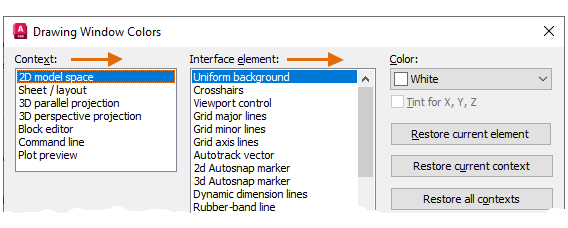
- Repeat step 2 for the Context, 3D parallel projection, using the same choices.
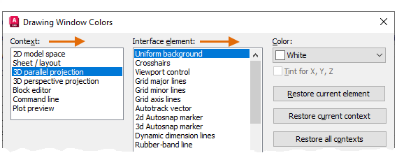
- Under Context, choose 3D perspective projection and make the choices indicated below.
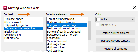
- Click Apply & Close and then OK.
Specify Perspective Views
Perspective views can be helpful for illustration, presentation, and rendering purposes. The illustration below displays a parallel projection along with a perspective projection to its right.
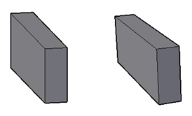
To switch to a perspective view, follow these steps:
- Click the second control, which might be set to [SE Isometric] or [Custom] and choose Perspective from the menu.

- Use the previous method where you press and hold Shift and the mouse wheel to change the view dynamically. Note that you can also use the scroll wheel to zoom in and out of the model.
- When you're done viewing in perspective, switch back to Parallel.
Temporarily Hide Objects that Obstruct Your View
Sometimes when you're viewing a model, objects can get in your way. In those situations, there's an easy way to temporarily hide those objects.
- Near the lower-left corner of the status bar, click Isolate Objects.

- From the menu, choose Hide Objects, select the three cylinders, and press Enter.
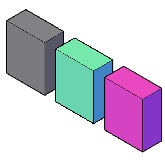
- Change the view dynamically as before. Then, click the same button and choose End Object Isolation to redisplay the cylinders.

Summary
With the three controls in the upper-left corner of every viewport, you can easily specify a viewing orientation and a visual style. You can also rotate a view in 3D dynamically using Shift and the mouse wheel to look for discrepancies in the model or create images for documents and presentations.
Command Line Controls for Viewing 3D Models
Here are the most commonly used commands and system variables related to viewing 3D models.
| Command | Description |
|---|---|
| 3DORBIT | Provides interactive viewing in 3D with the mouse. Right-click to display viewing options. |
| HIDEOBJECTS | Temporarily suppresses the display of selected objects |
| ISOLATEOBJECTS | Temporarily suppresses the display of all objects except those you select |
| OPTIONS, Display tab | The Color button displays the Drawing Window Colors Dialog Box |
| PLAN | Displays an orthographic view of the XY plane of a specified user coordinate system |
| UCSICON | Controls the visibility, placement, appearance, and selectability of the UCS icon |
| UNISOLATEOBJECTS | Displays objects previously hidden with the ISOLATEOBJECTS or HIDEOBJECTS command |
| VSCURRENT | Sets the visual style in the current viewport |
| System Variable | Description | Default Value | Saved In |
|---|---|---|---|
| DISPSILH | Controls display of silhouette edges of 3D solid and surface objects in the Wireframe or 2D Wireframe visual styles | 0 | Drawing |
| ISOLINES | Specifies the number of contour lines displayed on the curved surfaces of 3D solids | 4 | Drawing |
Use the AutoCAD Help system to learn more about these commands and their related system variables. You can experiment with the system variable settings to find what works best for your needs.